Other Parts Discussed in Thread: IWR1843, IWR6843AOP, IWR1443, IWR1443BOOST
IWR6843AOPEVM:
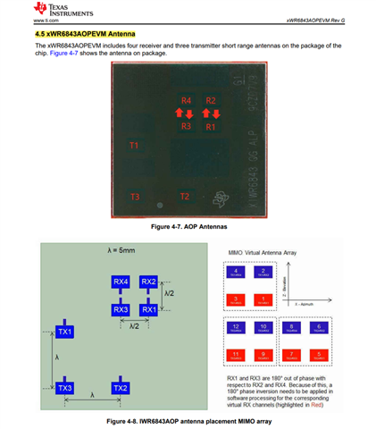
The antenna array shown in the figure is as follows:
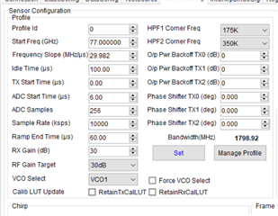
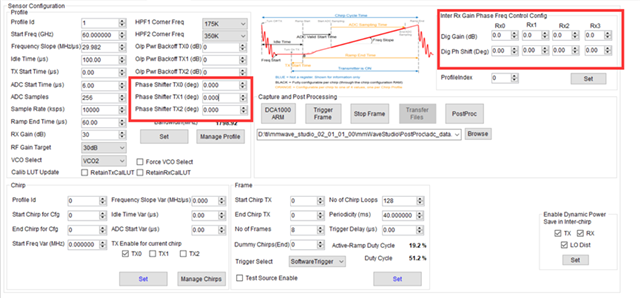
Based on the research, beamforming can be achieved by using phase shifters to adjust the phase of the transmit antennas. The modifications of mmWave studio are illustrated in the figure.For numerical calculations, the following code can be used to compute the phase shift values. The values to be filled in are the ones corresponding to "phaseTX_deg_wrap," Is my understanding correct?
theta_desired = -33.75;
m_ind = [0 1 2]; % antenna distance in units of lambda
phaseInc = 5.625; % step size for the phase shifter
phaseTX_rad = 2*pi*(m_ind*sind(theta_desired));
phaseTX_deg = (phaseTX_rad)*180/pi;
phaseTX_deg_wrap = wrapTo360(phaseTX_deg);
I have the following questions,
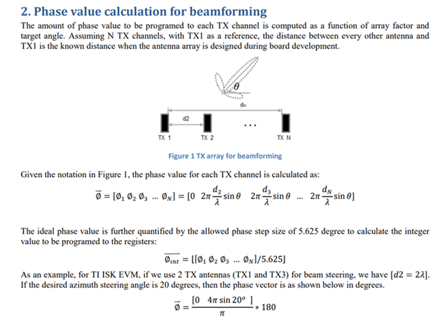
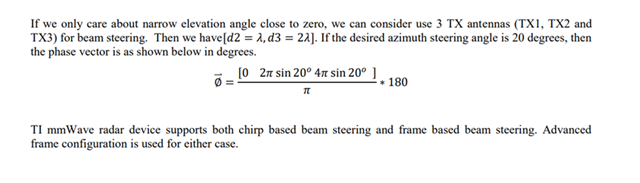
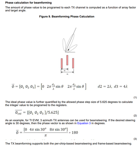
1."For two antennas, why is d2 twice the wavelength? For three antennas, it seems strange how d2 and d3 are calculated. When I referred to other antenna array layouts, like the IWR1843, they seem to implement TX beamforming as shown in the figure, where d2 and d3 become twice and four times the wavelength, respectively. I am confused about how to determine d2 and d3 for my device, IWR6843AOPEVM."
"Regarding configure1, how is it implemented?"
To summarize,
1.How to determine the phase shifter values (d) for the IWR6843AOPEVM in MATLAB to ensure the beam is directed to the desired angle.
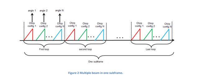
2.How to implement beamforming for multiple target angles in mmWave Studio.
3.Whether the calculation of the phase shifter values for receive antenna beamforming is similar to the code provided earlier.
Thank you, and I hope to receive your reply soon!