This thread has been locked.

If you have a related question, please click the "Ask a related question" button in the top right corner. The newly created question will be automatically linked to this question.

AWR2944: Questions regarding the CRC HW engine section 21.6 and regarding TI example

Part Number: AWR2944

Hello All

I hope you are fine

I would to ask a few questions regarding  the CRC HW engine section 21.6 in AWR294x Technical Reference Manual v1.0

I am intending to use the FULL-CPU mode, thus I would to understand the following:

1- In order to verify the CRC signature, the CPU can read from the PSA Signature Register and compare the calculated signature to the pre-determined CRC signature value

Question is: What is meant by the "pre-determined CRC signature value" and how is it calculated ?

Because in my design, the data stored in the memory are NOT deterministic data but rather changeable based on the radar measurements. So how can I get a pre-determined CRC value for them ?

2- When to use MSS_CRC base address and when to use DSS_CRC base address ?

As I see that the registers defined in "21.6.6 MSS_MCRC Registers" are only for MSS_CRC not DSS_CRC.

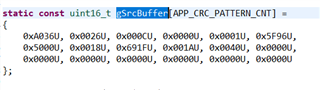
3- In TI CRC example located in mcu_plus_sdk_awr294x_08_06_00_28\examples\drivers\crc\crc_16bit

what is meant by gSrcBuffer ? is it just a data input example and that's it ?

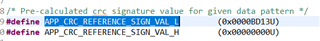
4- How did you calculated the value for APP_CRC_REFERENCE_SIGN_VAL_L and APP_CRC_REFERENCE_SIGN_VAL_H ?

I think that's it for now.

Please advise and many thanks in advance

  • Hi,

    Let me check on this internally and get back to you by next week.

    Thanks,

    Pradipta.

  • Hello Pradipta

    Thanks for your response

    Regarding the 1st question, please also advise for the AUTO-mode where no CPU is interacted with the CRC whole process. 

    Also I have another question no.5

    5- For the Semi-CPU mode, in which register can we find the bit flag for "Compression complete" after DMA transfer ?

    Many thanks in advance

  • Hi,

    Plese find my comments as below.

    1) Pre-determined CRC signature value is the CRC bit calculated (by the user) when you were storing the data originally onto a memory. Then once you transfer this data you can compare the signature value pre-determined and the newly calculated one to check for any discrepancy. 

    2) Both the MSS and DSS have one instance of CRC. When you want to use the MSS CRC hardware you will use the MSS address and vice versa. So, in MSS application code if you need to use the CRC engine/module you will use the MSS CRC module address. 

    Also, the DSS register is same as MSS one hence not listed out again in the TRM. Just the address is different, and both are mentioned in the TRM. 

    3) Yes, it is just an example data input to show the functionality of the module. 

    4) The data input is defined by us for the example code. So, we already know what the calculated signature value will. You can refer to the link below to understand more on how CRC works.

    Cyclic redundancy check - Wikipedia

    Thanks,

    Pradipta.

  • Hello Pradipta

    Many thanks for your answers

    Would you please also check my question no.5

    mentioned in my previous reply.

    I will re-mention it here again.

    ==> 5- For the Semi-CPU mode, in which register can we find the bit flag for "Compression complete" after DMA transfer ?

    Also I have another question:

    6- If there is no bit flag for "Compression complete" for Semi-CPU mode, then can we use the (CRC_BUSY Register) to notify that the data compression is completed in a way or another ?

    Again, many thanks for your reply. I really appreciate it.

  • Hi,

    1) For any of the modes you can refer to the comment added previously. 

    1) Pre-determined CRC signature value is the CRC bit calculated (by the user) when you were storing the data originally onto a memory. Then once you transfer this data you can compare the signature value pre-determined and the newly calculated one to check for any discrepancy. 

    2) This is an interrupt. It is also provided as part of Interrupt Offset Register. There is no bit defined in the CRC registers as you will directly get a interrupt for this so polling is not required on any bit. 

    Thanks,

    Pradipta.

  • Hello Pradipta

    Again, many thanks for your quick reply. Really appreciate it.

    Well in the current design, we think polling is better than interrupt since the system is very tight regarding the timing and the dynamic behaviour in general.

    7- Thus, can we use the bit flag CHx_BUSY in register CRC_BUSY for the Semi-CPU mode to notify that the data compression is completed in a way or another ?

    8- In order to use the Semi-CPU mode, can we set the bit CHx_MODE in register CRC_CTRL2 to be 1 0 ? Since it is mentioned as 'reserved' in the TRM 

    Please advise and many thanks for your time

  • Hi,

    7) Semi- CPU mode is designed to work with interrupts. CPU will be free to complete other tasks and once the interrupt comes it can verify the signature. IF you use polling then it will turn out to be full CPU mode only as the CPU is blocked and cannot complete other tasks. CHx_BUSY flags are update in the auto mode only as per the TRM. 

    8) No 10 is reserved. This cannot be done. 

    Thanks,

    Pradipta.

  • Hi

    Thanks for the answer

    In TI example "mcrc_semiCPU.c", in order to configure the SEMI-CPU, the example used the API SDL_MCRC_config to write the mode SDL_MCRC_OPERATION_MODE_SEMICPU= 0x02 (0b10) to register SDL_MCRC_CTRL2 in bits CH1_MODE

    I think this is contradicting with the TRM.

    Please advise

  • Hi,

    Yes, this is a typo in the TRM. For Semi-CPU mode 0x02 is correct. We will update this in the TRM. 

    Thanks,

    Pradipta.