Other Parts Discussed in Thread: INA303-Q1
Hi Team,
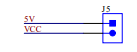
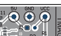
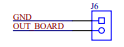
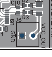
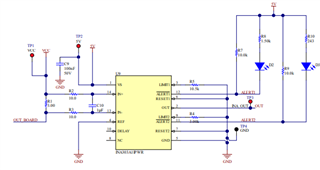
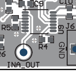
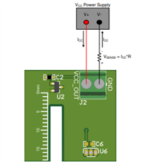
Schematic references are not matching with board design what is mentioned in the document. Could you please provide the document specific to PCB?
Thank You.
Original question:

Hi Team,
Schematic references are not matching with board design what is mentioned in the document. Could you please provide the document specific to PCB?
Thank You.