Hello Nathan,
The configuration you suggested did not work. Can you suggest alternatives
Regards
Vignesh
Original question:

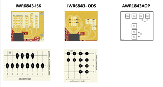
AWR1843AOPEVM: Runtime error : People Counting demo on AWR1843AOPEVM
Hello Nathan,
The configuration you suggested did not work. Can you suggest alternatives
Regards
Vignesh