This thread has been locked.

If you have a related question, please click the "Ask a related question" button in the top right corner. The newly created question will be automatically linked to this question.

TMAG5273: Application Questions

Part Number: TMAG5273

Hello,

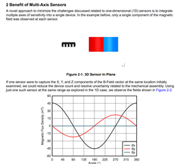
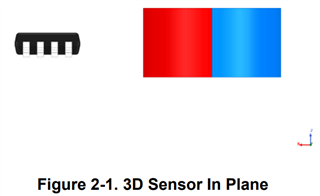
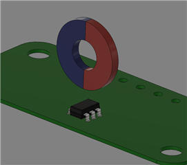
We are evaluating TMAG5273 for our application to detect the angle of a diametric ring magnet. For the given magnet/sensor orientation, would TMAG5273 be a capable sensor? Based on the Angle Measurement With Multi-Axis Linear Hall-Effect Sensors Application Note, my use-case seems similar to the In Plane scheme, with the sensor rotated 90 degrees. 

  • Would the internal angle measurement work best with the YZY mag channel configuration?
  • The datasheet specifies that reads need to be synchronized with the conversion update time to avoid reading data while the register is being updated. We cannot use the interrupt pin in our application, but would prefer to use continuous conversion mode. Are the registers in an undefined state when being updated? or is the worst case scenario that the MSB register is not from the same conversion as the LSB register?
  • What is the expected behavior of the sensor data registers if the magnetic field is stronger than the maximum sensitivity? Do they saturate or exhibit undefined behavior? During a quick test, I noticed the z-axis sensor data value jumping between ~20000 and ~100.
  • Hi Jeff,

    I am looking into your questions and will respond by end of day tomorrow.

    Best regards,

    Jesse

  • Hi Jeff,

    Thanks for your patience and thanks for posting to the Sensors forum.

    1. Yes, the internal angle measurement will work for this application. Based on your image, I you would use the XZX configuration. The pseudo simultaneous sampling can be used to equalize the noise floor when two sets of vertical sensor data are collected against one set of horizontal sensor data, as in XZX mode. It is possible that the X and Z field components measured from your spinning magnet will have unequal amplitude, so you may need to do some amplitude correction to help linearize your angle result. You can use the TI Magnetic Sense Simulator (TIMSS) to assist with magnetic simulation.


    2. If the result registers are read during an active conversion or update, they will return the data from the previous conversion. The note you are referencing in the datasheet is general guidance to avoid duplicating a reading.

    3. The sensor data registers will saturate when the magnetic field is stronger than the maximum sensitivity. Keep in mind that the result registers are a 16-bit 2's complement format in two 8-bit registers. 

    Best regards,

    Jesse

  • Hey Jesse,

    Thank you for your response. I have some follow-up questions to your response.

    1. From the application note linked in the original post, the X and Y axes are used as the magnet is presumably rotated about the z-axis. In our application, the sensor is rotated 90 degrees (about the y-axis) as compared to the sensor in the application note, which is shown in the provided image in the original post. This 90 degree rotation seems to only shift the z-axis to the x-axis, relative to the dimensions pictured in the application note. I'd like to understand why using the Z and X axes is the recommendation for measurement as opposed to Z and Y, given the example in the application note and our deviation from it.

    3. At certain points in the magnet's rotation the readings differ drastically. Here is an excerpt of some data collected at 10Hz. The magnet stationary with its south pole over the sensor.

    x:   -496; y:    580; z:  -8700; t: 30.26C
    x:     -4; y:    572; z:  -8696; t: 30.39C
    x:   -496; y:    576; z:     -4; t: 30.39C
    x:   -500; y:    568; z:    -12; t: 30.06C
    x:     -4; y:    564; z:     -4; t: 30.26C
    x:    -20; y:    572; z:     -4; t: 30.52C
    x:     -4; y:    576; z:     -8; t: 30.32C
    x:     -8; y:    564; z:  -8704; t: 30.46C
    x:   -512; y:    568; z:     -4; t: 30.46C
    x:   -508; y:    556; z:  -8704; t: 30.26C
    x:    -12; y:    580; z:  -8696; t: 30.39C
    x:   -512; y:    576; z:  -8696; t: 30.32C
    x:     -8; y:    576; z:  -8704; t: 30.26C
    x:     -4; y:    576; z:  -8704; t: 30.19C
    x:   -508; y:    580; z:  -8704; t: 30.39C
    x:   -512; y:    564; z:  -8704; t: 30.52C
    x:     -4; y:    588; z:  -8696; t: 30.32C
    x:     -4; y:    572; z:     -4; t: 30.46C
    x:   -512; y:    572; z:  -8700; t: 30.26C
    x:     -4; y:    600; z:     -8; t: 30.32C
    x:   -508; y:    564; z:     -8; t: 30.19C
    x:    -12; y:    564; z:     -8; t: 30.19C
    x:   -508; y:    564; z:     -8; t: 30.19C
    x:    -12; y:    576; z:     -8; t: 30.06C
    x:   -504; y:    568; z:  -8704; t: 30.32C
    x:     -4; y:    576; z:  -8704; t: 30.32C
    x:     -4; y:    576; z:     -8; t: 30.32C
    x:   -504; y:    576; z:     -8; t: 30.39C
    x:   -508; y:    580; z:     -4; t: 30.39C

    As you can see, the x-axis and z-axis readings are unreliable. I'd like to make sure there is no systematic mistake happening here. Here is our configuration settings. Mag gain and offsets have not been configured:
    DEVICE_CONFIG_1: 0x08 (4x averaging, no temperature coefficient)
    DEVICE_CONFIG_2: 0x1a (continuous mode, low noise mode, i2c glitch filter enabled)
    SENSOR_CONFIG_1: 0x70 (XYZ channels enabled)
    SENSOR_CONFIG_2: 0x03 (+/-266mT range on XYZ axes)

    When reading the sensor data, 6 bytes are read starting from X_MSB_RESULT, and each pair of bytes are byte-swapped (our system is little-endian). I am pretty confident there is no error in how the data is read from the registers.

  • Hey Jeff,

    1. My comments on the relevant axes used for angle calculation are regarding the direction of the sensitivity of the hall elements within the TMAG5273 package. The axes for the TMAG5273 are shown below in Figure 7-1 from the datasheet. Based on the rotating diametric ring magnet in your setup and considering the TMAG5273, the Z axis and the X axis magnetic fields would oscillate as the magnet rotates. This differs from what you pointed out in the app not because rather than being sensor-specific, there the X, Y, and Z axes are defined according to the legend in the bottom right of Figure 2-1. Note how the X and Y axes in Figure 7-1 are different from the X and Y axes as shown in Figure 2-1, while the Z axis is the same for both. For the TMAG5273, if the magnet is not perfectly centered above the device, you may see some oscillation on the Y axis as well, but the X and Z axes would be the most relevant for angle calculation.


    3. The device configuration settings you sent look good. One note is that 0x1A for DEVICE_CONFIG_2 would have the I2C glitch filter disabled. 0x12 enables the glitch filter.
    Can you provide more details on the setup you're testing such as what magnet you're using and its dimensions, how far away it is from the TMAG5273/how it's positioned above the device?
    For the data you shared, could you explain how you're converting the result register bytes to those values? Would you happen to have logic analyzer captures showing the byte values being read from the result registers? When relatively weak or no magnetic fields are present, it is normal for the two's complement result register values to move from small positive mT values to small negative mT values simply due to noise. 

    Best regards,

    Jesse

  • Thank you for your continued response.


    1. I see, so the graphic of the sensor in the application note does not depict any particular sensor, the user should determine the true sensor orientation from the axis diagram.

    3. You are also indeed correct about the glitch filter, 0 is enabled, 1 is disabled. After further analysis with a logic analyzer, there was indeed a bug in the firmware with how the bytes were being swapped. After fixing this, the sensor values are sane. Thank you for all of you help.

  • You're welcome, Jeff. Feel free to let us know if you have additional questions!

  • Hi Jesse,

    I would like to inquire about another topic related to the TMAG5273. As you mentioned, the axes need amplitude correction for the angle computation to work properly. We captured some XYZ data in a (relatively crude) test fixture and measured these values over a 225 degree rotation sweep (blue=X, orange=Y, green=Z).


    In the device datasheet, the procedure for amplitude correction describes rotating the magnet 360 degrees and measuring the peak-to-peak amplitude of the relevant axes. However in the end-user application, the magnet will only have +/- ~45 degrees (total of 90 degrees) of rotation. Do you have any suggestions for correcting the amplitudes in this use-case?

    We could try capturing some data in a more calibrated test fixture, or using the simulator. I wasn't able to get useful data out of the simulator when simulating a 360 degree rotation.


    It would be best if we could provide our user with a way to calibrate the sensor themselves with the limited range of motion, but we realize this may not be possible. Looking forward to your response,

    Jeff

  • Hey Jeff,

    The measured data looks a little off--as if the magnet and sensor aren't very straight/the magnet isn't perpendicular to the top of the package. Better alignment should provide better data.

    The 360 degree rotation for the amplitude calibration is to ensure that you capture the peak to peak amplitudes of the X and Z waveforms. The peak to peak amplitude difference should cause an angle error similar to Figure 2-7 below. If your magnet is centered at a 0 crossing (ex. 90 or 180 degrees in the graph below), meaning one of the magnet's poles is aimed directly at the sensor, then rotating +/- 45 degrees would give relatively linear angle error. Otherwise the angle error would be less linear. This app note provides more details on different angle error sources and a lookup table calibration method for linearizing the angle error in section 6. 

    There are some bug fixes for the simulator (TIMSS) that are in the process of being resolved--I believe the bug you are seeing is due to the rotation of the magnet. Try leaving the magnet origin positions set to 0, and move the sensor instead. I've attached a json file that I believe matches your setup--simply import it by clicking "Import design file" on the TIMSS home screen. You can tweak the sensor position and magnet dimensions/properties as needed.

    {
      "design_name": "TMAG5273_ring",
      "magnet_id": 4,
      "poles": 2,
      "material_id": 1,
      "grade_id": 1,
      "select_remanence": "br_average",
      "remanence": 1200,
      "temperature": 20,
      "temperature_coefficient": -0.12,
      "coercivity": 12,
      "function_id": 4,
      "magnet_geometry": {
        "outer_diameter": 5,
        "inner_diameter": 3,
        "height": 1
      },
      "magnet_position": {
        "x_position": 0,
        "y_position": 0,
        "z_position": 0
      },
      "magnet_angle": {
        "x_angle": 0,
        "y_angle": 0,
        "z_angle": 0
      },
      "magnet_movement": {
        "arc_length": 360
      },
      "sim_setting": {
        "angular_step_size": 0.5
      },
      "custom_inputs": {
        "variant": "A1",
        "package": "SOT23-6",
        "applied_vcc": 3.3,
        "maximum_input": 40,
        "temperature_compensation": 0,
        "averaging": 1,
        "bop": "bop_typ",
        "brp": "brp_typ"
      },
      "sensor_position": {
        "x_position": 0,
        "y_position": -5,
        "z_position": 0
      },
      "sensor_angle": {
        "x_angle": -90,
        "y_angle": 0,
        "z_angle": 0
      },
      "user_design": 1403,
      "sensor_id": "TMAG5273"
    }

    Hope this helps--let me know if you have additional questions.

    Best regards,

    Jesse