This thread has been locked.

If you have a related question, please click the "Ask a related question" button in the top right corner. The newly created question will be automatically linked to this question.

LDC0851: Understanding coil design parameters for the LDC0851HDSGT to exploit sensing distance and reliability

Part Number: LDC0851
Other Parts Discussed in Thread: , LDCCOILEVM, LDC1612, LDC1101

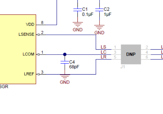
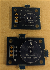
I have a project that uses a steel plate ~ 8" in diameter and is .125" thick. This plate sits orthogonal to the product and eventually falls ~ 90 degrees coming to rest ~20mm above the product. The goal is to detect when the plate has fallen and initiate a reset of the plate to the previous orthogonal position. I am looking for design guidance on the optimal coil for this sensing application and the optimal position of the sense and reference coils. I have approximately 1" of depth in the packaging and could increase that by .5 inches if needed. The top cover of the product is ~ 3" wide and 5" long and is rectangular. Conceivably a coil could be integrated into the cover and a reference coil into the base but that will also have a cost impact as well. Ideally having both coils on a PCB mounted as close to the target as possible would be ideal but may not be optimal for the sensing distance required. I was looking for someone that has experience with this product and can advise beyond the datasheet. Currently the product has been tested with externally actuated hall effect switches and normal microswitches but eliminating them is desirable if cost can be managed. Ideally the output of the LDC0851HDSGT would drive a mosfet gate, but power management could be done in other ways as well. If custom coils are recommended can you provide wire or trace dimensions and layout for a favorable result?

Edit: Additionally the material used for the enclosure during prototyping will be PETG and likely ABS or PC/ABS in production. It is also battery powered so consideration to optimized coil design for a battery power source would be helpful. Sample rate will be very low. Every 10 seconds the micro will wake the sensor look for a fallen plate and either reset a fallen plate, or go back to sleep.

  • Hi William,

    Typically, you can achieve max range of about 40% of the coil diameter in a side by side configuration when the coils are well matched.  The max coil size that the LDC0851 will be able to drive and properly oscillate is around 50mm.  This would put the max range right around 20mm, which leaves little or no margin based on your current configuration.  In the top cover, you could fit 50mm side by side coils, but I would suggest to see if there is a way you could also place these coils closer to the target. 

    You can find information about coil design in the app note below.  

    https://www.ti.com/lit/an/snoa930c/snoa930c.pdf

    We also offer a design tool, which is useful for designing and estimating your coil characteristics.  

    https://www.ti.com/tool/LDC-DESIGN-TOOLS 


  • Eddie,

        Thank you for your reply. In order to optimize the delta between an the two coils wouldn't it make more sense to NOT have them be side by side with a large steel plate over both? Would it not be better to have the sense coil in the top of the cover and a reference coil in the bottom? What coil design parameters are you suggesting for a 50mm coil? Are you talking about magnet wire coils around a 50mm form? If so, how does the diameter of the wire and number of wraps affect circuit operation? I am not an EE so I am speaking from a position of genuine ignorance here. That is why when I contacted TI I asked for a person really familiar with this product so I could shorten my experimentation as much as possible. What would happen if I designed a PCB coil that simply used a cheap 2 sided board with coils 50mm in diameter, one side clockwise the other counter clockwise with a center via. One of these boards would get mounted to the inside of the top cover, the other to the bottom. Would that create greater differentiation for this device? Have you experience with a similar approach?  

  • William,

    Yes, if the steel plate is covering both coils, side by side could be a problem.  Another approach is too use a stacked coil, but range will be reduced in this configuration.  In a stacked configuration, max range is expected to be ~30% of the diameter.  In order to maximize the range, the sensor separation between PCB layers is important.  See section 3.3 of the app note below.  Your suggestion of using 2 coil boards where the cover provides additional separation should work well. 

    https://www.ti.com/lit/an/snoa982/snoa982.pdf

    In all cases, we are discussing PCB trace coils.  Wirewound can work, but the matching of the 2 coils will likely be worse than PCB traces can produce, reproducibility is tough with wirewound, and temperature will affect the inductance more.  The number of turns really does not affect the range.  The main factor for range is the size of the coil.

    The tool below can be used to generate the design files for a coil with your specification.  I have included one such example for a 50mm coil.

    https://webench.ti.com/wb5/LDC/#/spirals     

    50mm example: https://webench.ti.com/wb5/LDC/#/spirals?shape=Circular&lcTanKCapacitance=1000&turns=6&layers=4&spaceBetweenTrace=5.98&traceWidth=5&copperThickness=1.000&dout=787.4&temperature=25&partno=LDC0851&voltage=1.8&x12=8.00&x23=36.60&x34=8.00

  • Thank you again Eddie,

        I spent the day with the snoa982.pdf yesterday. It was a bit of a slog through for me but I took what I learned from that document and played with the design tools that are excel based. From that purely theoretical experience I have arrived at the following conclusions (Please don't hold back if I'm in the weeds):

    1. At ~ 50 mm Square or Round are pretty close to each other in performance.

    2. 16-20 coils really does the job according to the design tools, again assuming a pretty big coil.

    3. Might not be much benefit to using a coil on both sides of the board if the L and R are within design limits. This actually seems to play to really large coils.

    I also spent some time last night really studying the kinematics of the entire assembly. What I noticed was that the plate does not actually fall flat against the top of the housing. It is actually currently only a few mm away on one end, and 30 mm away on the other. I *might* actually get away with A. a smaller set of coils, and B. a single PCB with the microcontroller, battery management, and MOSFET in the middle of the PCB and the coils at the ends. This may actually play out pretty well.

    Thank you for guiding me down the path of enlightenment and not "doing my homework for me". I'm better off for the experience.

    Do you know of a source for cheap PCB coils for experimenting? Maybe someone has a PCB milling CNC machine set up for this sort of thing? The list of quick turn inexpensive board houses seem to all have "free" online layout tools. None of which seem to be compatible with the CAD output of the design tools. Any tips here will be greatly appreciated. 

  • Hi WIlliam,

    Sorry for the delay.  The forum was down for maintenance Thurs/Fri.  See my notes below.

    1. Yes, they will be similar.  Generally, circular provides a slightly better performance.

    2. Yes, 16-20 turns can be enough for larger coil sizes.  Additional turns wont really increase range.

    3.  Sure, on larger coils, you can likely have enough board space to get the proper number of turns on 1 side of the PCB.  

    I recommend testing with the LDC0851EVM, which comes with a 20mm coil, which may already meet the shorter range of a few mm.  The EVM also allows you to break off the coil and attach your own.  

    https://www.ti.com/tool/LDC0851EVM 

    We also have a LDCCOILEVM which includes many different coils.  I am currently testing with the 46mm coils and see good range 30-40mm, but it is a bit unstable as these coils weren't really intended for use with LDC0851 where a reference coil is required.  I will work improving this over the next couple days and let you know what kind of stable read range I can obtain.  

    https://www.ti.com/tool/LDCCOILEVM 

  • Eddie,

         First of all THANK YOU for staying with me on this. I went dark there for a while as I had field work to tend do. The life of a YouTuber never gets dull. Lol.

    As I am funding this research project by myself, is there a discount path for us die hard experimenters/entrepreneurs? $200 clams is a chunky spend when the Boss isn't picking up the tab. Let me know, I was looking at the mechanical design again and I have an idea that seems like it will make this dirt simple to implement. I'm anxious to get it in play and kick the micro switch I'm currently using to the curb. This will be SO MUCH more elegant. and in the end, cost effective. I'll wait to hear back from you before pulling the trigger.

    Bill

  • Hi Bill,

    Unfortunately, we do not have any discounted tools for experimenters/entrepreneurs.  

  • Not even a coupon code?

  • Bill,

    No, I am not aware of any coupon code.  We don't really target low cost for the evaluation boards.  You could also consider looking at a third party board.  I am not aware of one for the LDC0851, but seeed studio has one for the LDC1612, which does enable higher performance and features than the LDC0851, but it does require I2C for communication.  They do also have Arduino code available.  

    https://www.seeedstudio.com/Grove-2-Channel-Inductive-Sensor-LDC1612.html 

  • Thank you Eddie.

  • Hello Eddie,

       I got my kit and two of the PCB's of alternative coils that you also linked to. I assumed, incorrectly, that the alternate coils could be swapped out for the 20mm coil that come with the eval kit. The 20mm coils on the eval board are effectively two separate coils, one a sense and the other a reference. The break away board that contains the two 20mm separate coils seems to not have a capacitor on it so that is probably on the middle PCB. The board with the different sized coils seems to have a coil on each side that are connected to one another and pads for a separate capacitor. What would be the simplest solution to experiment with different coils given the available hardware? With the 20mm coils I actually have way more range than I actually need, and a smaller diameter would serve me better as well from a packaging standpoint. I was delighted that the eval board worked so well, it was crazy good! Would like to refine it now and you seem like the guy to ask. Your thoughts?

  • William,

    Glad to hear you are seeing good performance with the EVM!  Yes, the LDCCOILEVM is really intended for single coil devices like the LDC1612, LDC1101, etc.  I was able to make it work with 2 of the 46mm coils, but the performance was unstable.  It may work better with the smaller coils in that kit that have lower inductance, but I think you will be better off with a custom designed coil or I can ship you something I have available as mentioned below.  

    I do have a few reference coils for LDC0851 which use the stacked coils design similar to the EVM.  I believe there are some 10mm coils and small rectangular shapes.  I will check what I have available when I am at my desk later today and let you know what form factors I have.  I can ship you 1 or 2 coils that you can test directly connected to the EVM.  You may need to change the capacitor to achieve the frequency you would like to use.  On the EVM, this is C4(68pF).


  • THAT WOULD BE AMAZING Eddie! Thank you. 15 to 10mm would be perfect! 

  • I have 2 coils that I think may work well for you.  One is 15mm and the other is 10mm x 7mm. 

    I will send you a "friendship request" where you can provide your address.