Other Parts Discussed in Thread: TDC1000
Hello,
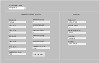
I am using the TDC7200 in combination with the TDC1000 in measurement mode 2 to do a flow measurement. I am getting a start and a stop signal, but TIME2 register stays 0. The overflow registers say, that there was no overflow. So why stays the timer zero or is it possible that the component is broken?
Best regards
Anna-Lena

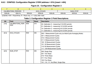

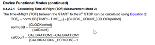 (Datasheet page 16)