


Dear TI:
Due to research needs, we modified the antenna array of the AWR-RF-EVM board (the DSP-EVM board remains unchanged). The frequency point of the new antenna array is 79 GHZ and the array is sparse (the spacing between antennas is not an integer multiple of λ).
We then implemented channel calibration following the MIMO calibration flow in mmWaveStudio. Here is our calibration process, results, and problems:
(1) Operation process:
step1:
First, since the antenna frequency point has been changed (the self-designed antenna is 79Ghz), we are not sure whether the MIMO calibration parameters given by TI officially are still applicable. Second, the calibration formula in the TI manual does not give the effect of the starting frequency point on the calibration result (as shown in Figure 1). Finally, we chose to change the starting frequency parameter in the calibration file from 77 Ghz to 79 Ghz. Consequently, due to the bandwidth limitation, the other parameters were changed accordingly. The entire parameter changes are shown in Figure 2. :
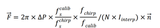
Figure 1 the calibration formula
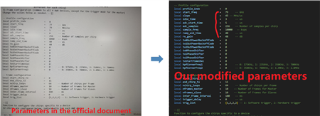
Figure 2 parameter changes
step2:
We follow the manual process: first place a corner reflector at a distance of 5m, then use mmstudio to capture the data, and then use MATLAB cascade_MIMO_antennaCalib.m to process to obtain the final calibration. mat file.
step3 :
After running the matlab program, the calibration .mat file and point indexing results were obtained (shown in Figure 3)
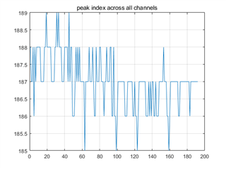
figure 3 point indexing results
step4 : We used the generated .mat file as the calibration file during signal processing.
(2)Test results:
When we applied it, we realized that the imaging results were very bad and strange:
When we use the same parameters to capture the corner reflector 5m away directly in front of the radar, we get a good RAM image as shown in Figure 4. The peak at the target is much higher than the side flap and the peak energy is concentrated. However, under the same conditions, when we move the corner reflector away from the center of the radar (For example,10°), the results of the RAM image are very poor, the target is barely visible and the energy is dispersed, as shown in Figure 5. We don't understand why this is a problem.
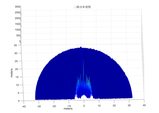
figure 4 corner reflector at the center
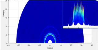
figure 5 corner reflector off-center
(2)Our questions:
1.Why is this phenomenon that imaging is only valid when the target is at the center of the radar, and is there a problem with the calibration process?
2.We have questions about the calibration parameters; when our antenna becomes 79 GHz, will the original 77 GHz parameters apply? Are we making the right changes to the parameters?
3. Does TI's MIMO calibration process apply to sparse arrays?
4. What can we do to make the calibration work (generate good imaging images)?
Hope to get a reply, thanks a lot!
