This thread has been locked.

If you have a related question, please click the "Ask a related question" button in the top right corner. The newly created question will be automatically linked to this question.

IWRL6432BOOST: UART_isRxRdy function read taking long time

Part Number: IWRL6432BOOST

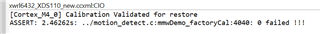
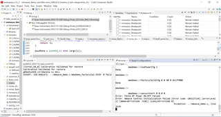
I was trying to run the mmwdemo project from MMWAVE_L_SDK 5.3 through CCS. I found that I am getting some print like [Cortex_M4_0] Calibration Validated for restore waited for sometime and Iam not able to see anything after that. I have debugged that the code is running in the function "UART_readPolling" and nothing after that. 

Should there be any waiting time for the same. 

How to debug this issue?

Also found that not entering this if condition also 

if(UART_isRxRdy(object->pSCIRegs))
{
UART_rxChar(object);
}

Please help us to debug the same as it is important for our next development to proceed. 

  • Hello.

    The output message is fine, that indicates the device started properly.  The reason it is holding up is because it is waiting for you to send the configuration commands via UART.  Try sending a configuration file through a serial terminal or through the industrial visualizer.

    Sincerely,

    Santosh

  • Hi Santhosh 

    Should we provide the cfg file present in profile folder of the demo.Like there is .cfg file named parking_5m.cfg in that folder. So while running executable on the board do we need to profile this file name through the uart?

    One more thing, while debugging it is looping inside the uart_readpolling and there is a if block inside that 

    if(UART_isRxRdy(object->pSCIRegs))
    {
    UART_rxChar(object);
    }

    and it’s not entering inside this if block means UART_isRxRdy(object->pSCIRegs) is getting false always. We waited for a long time it its looping. Does that means the Rx is not ready?

    Are we missing anything, can you provide a walk through to how to run a example demo provided in the MMWAVE_L_SDK_05_03 on board IWRL_6432

    Reagards

    Sreekesh Giri

  • Hello.

    Should we provide the cfg file present in profile folder of the demo.Like there is .cfg file named parking_5m.cfg in that folder. So while running executable on the board do we need to profile this file name through the uart?

    You are correct, pass in that configuration file to the device via UART. 

    Does that means the Rx is not ready?

    Yes.  This function is continuously reading and waiting for information in the Rx, so until Rx is "ready" with information it won't read from there.

    Are we missing anything, can you provide a walk through to how to run a example demo provided in the MMWAVE_L_SDK_05_03 on board IWRL_6432

    Please look through the presence and motion user guide under the presence and motion example project on the Radar Toolbox.  This guide walks through how to start a project in the MMWAVE_L_SDK_05_03 for our low power devices.

    Sincerely,

    Santosh

  • Hi

    One more doubt. Now we are running the board in the debug mode and we are only connecting USB should we need to connect 5V/3A Power also.
    And also when I don't need to run the Low Power mode visualizer and how we will know when config should be given through the UART.  Is there any message will come in the console?

    What should be the mode of the board while running the executable. ?

    Regards
    Sreekesh Giri

  • Hi
    There is macro named CLI_BYPASS. By defining it I was able to send the configuration as hard coded strings. But still the below error is showing.

    retVal = MMWave_factoryCalibConfig(gMmwMssMCB.ctrlHandle, &factoryCalCfg, &errCode);
    if (retVal != SystemP_SUCCESS)
    {

    /* Error: Unable to perform boot calibration */
    MMWave_decodeError (errCode, &errorLevel, &mmWaveErrorCode, &subsysErrorCode);

    /* Error: Unable to initialize the mmWave control module */
    CLI_write ("Error: mmWave Control Initialization failed [Error code %d] [errorLevel %d] [mmWaveErrorCode %d] [subsysErrorCode %d]\n", errCode, errorLevel, mmWaveErrorCode, subsysErrorCode);
    if (mmWaveErrorCode == MMWAVE_ERFSBOOTCAL)
    {
    CLI_write ("Error: Boot Calibration failure\n");
    ateCalib->validityFlag = 0x0U; /* Flag to indicate to re-run ATE calibration */
    }
    else
    {
    MmwDemo_debugAssert (0);
    }
    }

    here  MmwDemo_debugAssert (0); is the line number 3536 mentioned in the error message. What is the reason behind this.
    Also still not got the idea of how to give config file through UART. While commenting the CLI_BYPASS macro the below message is coming the UART.

    [Cortex_M4_0] Calibration Validated for restore 

    and it still like this for several minutes while pausing and putting the breakpoints I was able notice that it is looping around that UART_ReadPolling()
    I have gone through the User Guides you specified and I didn't get any info on how to give config file or where should I place it. I am using CSS1240 in LINUX. Confused at what I am missing!.

    Sincerely,

    Sreekesh Giri


  • We were seeing this error while running mmw demo and motion detection demo in CCS.

    Sometimes we were seeing this "Error: FECSS RF Power ON/OFF failed"  "Error: mmWave Control Initialization failed [Error code -203227134] [errorLevel 2] [mmWaveErrorCode -3101] [subsysErrorCode 0]
    Exception: ../motion_detect.c, line 4040."

    Sometimes Iam facing this error 

    Boot calibration error 

    what might be the issue. I started with flashing only empyt release app image. later tried to run the .out files for mmwdemo and motion detection from CCS with the compiled file. 

  • how we will know when config should be given through the UART.

    As soon as the device is put into functional mode and powered on, it will be waiting for the configuration commands.  You won't see any output on the console.  However, once you send the configuration commands, you can see the radar output on the serial terminal.  To run the executable, you will need to switch the board into functional mode.

    Sincerely,

    Santosh

  • Hello.

    I have gone through the User Guides you specified and I didn't get any info on how to give config file or where should I place it

    Please look at section 6 in the presence and motion user guide for instructions on how to send the device configuration.

    "Error: FECSS RF Power ON/OFF failed"  "Error: mmWave Control Initialization failed [Error code -203227134] [errorLevel 2] [mmWaveErrorCode -3101] [subsysErrorCode 0]

    This error can happen if the configuration being passed produces invalid values in the data-path.  Often times the best way to fix this is to step through the data-path and determine where it is failing, and often times it will indicate which configuration value was incorrect.  In addition, you may have to reset your device before restarting a debug session, as this error can pop up if not reset before the next debug session is started.

    Sincerely,

    Santosh

  • Hi Santhosh

    We have entered the configuration through UART but after the SensorStart the following error is happening


    Even in CLI_BYPASS enabled mode. While debugging it error happens in the code mentioned below

        retVal = MMWave_initLink (&gMMWave_MCB, errCode);
        if (retVal < 0)
        {
            /* Error: Failure to open the mmWave Link; error code is already setup. */
            goto exit;
        }

    at this is inside MMWave_init() which return a MMWave_Handler but due to the error

    gMmwMssMCB.ctrlHandle = MMWave_init (&initCfg, &errCode);

    this gMmwMssMCB.ctrlHandle is a NULL pointer.

    For the clarity the MMWave_initLink contain a block as shown below

    if (MMWave_initMMWaveLink (ptrMMWaveMCB, errCode) == 0)
    {
    /* Successfully initialized the mmWave Link: */
    retVal = 0;
    }
    else
    {
    /* Error: Unable to setup the mmWave Link */
    retVal = MINUS_ONE;
    }


    While debugging the flow of the program is going to the else part and inside the MMWave_initMMWaveLink() function there is if block as shown below
    retVal = (int32_t)MMWave_LinkInitCommon(ptrMMWaveMCB, errCode);
    if (retVal != M_DFP_RET_CODE_OK)
    {
    retVal = MINUS_ONE;
    goto exit;
    }

    in which the the if condition is true which means that link setup is not successful. Does this error occurred to you???


    Sincerely,

    Sreekesh Giri


  • Hello Sreekesh.

    As I stated before, there is an issue with the hard-coded configuration that is provided in the presence and motion demo.  Please copy in the configuration from one of configuration profiles in the profiles folder(<sdk-install-path>\examples\mmw_demo\motion_and_presence_detection\profiles\xwrL64xx-evm) in the sdk and see if that fixes that error.

    Sincerely,

    Santosh

  • Hi

    I have given the cofig params as mentioned in MMWAVE_L_SDK_05_03_00_02/examples/mmw_demo/mmwave_demo/profiles/xwrL64xx-evm/parking_5m.cfg as shown below.

    Is that right? Or is there any method to load the cfg file itself through the UART.
    We have given  all the configurations as mentioned in cfg file still the gMmwMssMCB.ctrlHandle = MMWave_init (&initCfg, &errCode);  is creating NULL pointer.


    Sincerely,

    Sreekesh Giri

  • Hello.

    That looks correct.  It looks like there are no issues from the configuration.  I urge you again to please go through the user guide as it contains information on how to set-up and configure the device as there is a specific section in the user guide that describes this process(section 6).

    Or is there any method to load the cfg file itself through the UART.

    As I have stated before, please utilize the industrial visualizer in <radar-toolbox-install>/tools/visualizers/Industrial_Visualizer/ to access the tool that will allow you to select configuration files and send them to the device without having to type into a terminal.  However, if this is happening, be sure to remove/comment out the CLI_BYPASS flag definition so that the device waits for the CLI via UART.

    Sincerely,

    Santosh

  • Hi Santhosh


    Please copy in the configuration from one of configuration profiles in the profiles folder(<sdk-install-path>\examples\mmw_demo\motion_and_presence_detection\profiles\xwrL64xx-evm) i

    ├── MotionDetect_1TX-1RX.cfg
    ├── MotionDetect_1TX-2RX.cfg
    ├── MotionDetect.cfg
    ├── PresenceDetect.cfg
    ├── TrackingClassification_HighBw_4Ant.cfg
    └── TrackingClassification_MidBw.cfg
    these are the config files available in the the folder you mentioned. Which one should i use and can I use these ones for running the mmwave_demo project available in the mmw_demo folder?.


    Do you have any suggestion regarding the errors, mentioned below.

    Error: FECSS RF Power ON/OFF failed, where this is happening inside the CLI_MMWaveSensorStart and
    Error: mmWave Control Initialization failed [Error code -203327134] [errorLevel 2] inside the mmwDemo_mmWaveInit function.


    Regards,
    Sreekesh Giri


  • Which one should i use and can I use these ones for running the mmwave_demo project available in the mmw_demo folder?.

    These profiles are meant for the motion and presence example in the SDK.  If you want the profile for the mmw_demo, look in the profiles folder of the mmw_demo for appropriate configurations.

    Do you have any suggestion regarding the errors, mentioned below.

    This indicates that there is something wrong with the chirp configuration that you are using, and the incorrect configuration will not allow the device to start.  Double check that your configuration is correct and valid via the sensing estimator, although this error should not occur if you use the chirp configurations provided in the SDK.

    Sincerely,

    Santosh

  • Hi Santhosh, 

    The few points I came to know from this discussion is:-

    1. The mode to be used is functional mode for CCS debug also. 

    2. Empty image is flashed on the board through CCS and the presence detection locally build .out is run on the board through CCS. 

    3. Can try the configuration file of presence detection from SDK through UART. 

    The doubts still we have is :- 

    1. The UART - USB connection is the only connection we have on the board. Do we need to connect the power 5V/3A power supply? and is there any connection also need for debugging using CCS?

    2. We have another CCS project created for our development, we are trying to port that into the mmwdemo project and build it successfully. And connected the target in Cortex M4.0. we got message of "Calibration validated for restore". I opened a terminal UART from the CCS, the baud rate selected is 115200. Is this correct?

    3. We were sending the configuration commands there and we used to get message like this now: -

    Cortex_M4_0: JTAG Communication Error: (Error -1170 @ 0x0) Unable to access the DAP. Reset the device, and retry the operation. If error persists, confirm configuration, power-cycle the board, and/or try more reliable JTAG settings (e.g. lower TCLK). (Emulation package 9.10.0.00080) 
    Cortex_M4_0: Failed to remove the debug state from the target before disconnecting.  There may still be breakpoint op-codes embedded in program memory.  It is recommended that you reset the emulator before you connect and reload your program before you continue debugging

    what might be the issue?

    4. If we run the board with .out from CCS, and to send configuration we are using any visualiser then we need to terminate  the session from CCS and then only we could be able to connect through the visulaiser right? Is anything I missed here?

    Can you please point out what all points or steps we missed here ?

  • Hello,

    1. The UART - USB connection is the only connection we have on the board. Do we need to connect the power 5V/3A power supply? and is there any connection also need for debugging using CCS?

    USB is the only connection required. If USB port on your PC does not output enough power then external power can be supplied via the barrel jack connector but typically this should not be required.

    2. We have another CCS project created for our development, we are trying to port that into the mmwdemo project and build it successfully. And connected the target in Cortex M4.0. we got message of "Calibration validated for restore". I opened a terminal UART from the CCS, the baud rate selected is 115200. Is this correct?

    The 'Calibration validated for restore' message is expected and indicates successful boot calibration. The demo boots with baud rate of 115200 so this should be correct if you haven't modified this in the demo code.

    3. We were sending the configuration commands there and we used to get message like this now: -

    This message indicates the JTAG connection between the device and CCS has been dropped. The reason for this is likely due to the configuration that you are sending. Does your configuration contain lowPowerCfg 1? With low power modes enabled the device goes into 'deep sleep' mode at the end of each frame period. In doing so, all of the peripherals are shut off or clock gated and this causes the JTAG connection to be dropped. The demo continues to run on the device so you may have noticed data output continues if you are connected to a UART terminal or visualizer. To avoid this, it is recommended not to use 'lowPowerCfg 1' when running the demo in CCS. There are 2 options. The first option is to use 'lowPowerCfg 0' which disables deep sleep. The second option is to use 'lowPowerCfg 2' which enables low power emulation mode, in which the execution flow is the same but peripherals are not shut down (device does not enter deep sleep).

    4. If we run the board with .out from CCS, and to send configuration we are using any visualiser then we need to terminate  the session from CCS and then only we could be able to connect through the visulaiser right? Is anything I missed here?

    If I am understanding the question correctly then no, this is not required. You are able to run the demo in CCS (connected via JTAG) while also connected to a visualizer or serial terminal (connected via UART). 

    Best Regards,

    Josh

  • Sorry, I have only connected the UART now, so to communicate both the CCS and visualiser we would require JTAG connection as well?

    Can you show us how the connection should be?

  • Hello.

    so to communicate both the CCS and visualiser we would require JTAG connection as well

    As long as you have the switches for the IWR6432Boost EVM set correctly, JTAG connection should be set up correctly.  The EVM Operational Set Up Modes guide should show you what the switches should be for functional mode, which will allow you to connect to CCS while also running the visualizer.  I have included an image here for reference.

    As Josh mentioned earlier, also check to make sure that you have either lowpowercfg 0 or lowpowercfg 2, which disables and emulates low power mode, respectively.  If you are using lowpowercfg 2, this will allow you to continue running the debugger while in "low power mode".  If you have lowpowercfg 1, then your device will enter actual low power mode, which results in the debugger getting disconnected.

    Sincerely,

    Santosh