This thread has been locked.

If you have a related question, please click the "Ask a related question" button in the top right corner. The newly created question will be automatically linked to this question.

FDC1004: FDC1004 not linear for liquid in sponge

Part Number: FDC1004
Other Parts Discussed in Thread: FDC2214

After the recommendation in e2e.ti.com/.../4712109 to use FDC1004 instead of FDC2214, I am trying to replicate our results using FDC1004.

We are using oil in our product and our application requires our liquid to be held in a sponge, meaning that it doesn't fall to the lowest level under gravity. The application is liquid level sensing (like TI’s coffee machine water reservoir example).

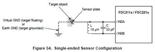
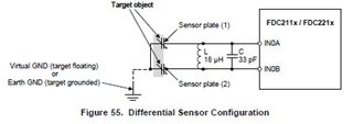
We use 2 sensors (2 measurements), which are very similar but we haven’t ensured they are identical. Each plate as large as our reservoir, one on one side of the reservoir, and the other plate on the other side. Each plate is attached to 1 measurement channel, ie single-ended.  The used value is the sum of the 2 measurements.  (Specifically for FDC1004 its CHA_CINx  and CHB_CAPDAC  where CAPDAC=0)

There is a ground wire held securely in the middle of the reservoir, touching the liquid.


To start the test, our sponge is dry, and we fill it up in discrete steps until the reservoir is full. Both chips correctly measure the incremental volume of liquid and the results are linear (r squared >0.95 for measurement values vs weight gain)

When we drain the reservoir (by squeezing liquid of out the sponge), the FDC2214 returns linear values as the weight decreases. This is correct and as expected.

However, the FDC1004 continues to return values as if the reservoir was near it’s maximum level.

For example, I fill from 0g to 3g of liquid. Then I drain in increments from 3g down to 0.5g of liquid and the FDC1004 returns values corresponding to 3g down to 2.5g.


I’ve also tried this with water in the sponge, and I get similar results. Ie when the sponge is wet, a reduction in weight is not registered.


If we don’t use a sponge in the reservoir (and hence the liquid is pulled down by gravity), both chips (FDC2214 and FDC1004) are able to correctly measure the decrease in liquid from 3g down to 0g.


Have you ever seen anything like this before?

Could you explain why the FDC1004 is not able to correctly read the liquid level of a wet-but-mostly-empty sponge?

Thank you.

  • Haydn,

    Thanks for the thorough description.

    Some questions:

    1. Do the FDC2214 and FDC1004 use the same sensors?
    2. How are the sensors configured and connected to the two devices?
    3. How is the ground wire configured/connected to the tank contents?
    4. What is the sensor frequency for the FDC2214?
    5. What are the capacitance readings using the two devices for full & empty tanks with and without sponges?

    Regards,
    John

  • Hi John,

    1/ Do the FDC2214 and FDC1004 use the same sensors?

    Yes, the PCB is connected to the sensor plates with 2 wires about 20mm long.  I unsoldered the FDC1004 board, and soldered the FDC2214 board to the sensor plates at the same place. So I’ve reused the same reservoir and sensor plates.

    2/ How are the sensors configured and connected to the two devices?

    As mentioned, just soldered from plates to the PCB. The PCB is underneath the reservoir,

    3/ How is the ground wire configured/connected to the tank contents?

    There is a potential-free metal collar in the centre of the reservoir, with a coil inside that. It’s held in place by the collar and I’ve grounded the one end of the coil with a wire sticking out the top of the reservoir. The liquid is in contact with all of that, so the liquid is touching the coil = ground.

    The sensor plates are on the outside of the reservoir and not touching the liquid.

    4/ What is the sensor frequency for the FDC2214?

    I would assume around 8MHz, but I’ll have to double check that and get back to you.

    5/What are the capacitance readings using the two devices for full & empty tanks with and without sponges?

    I don’t convert to capacitance, I just use the raw data values. Here are the configurations and values.


    FDC2214 setup

    The FDC2214 channels are all configured like this:

        channel_settings[0].RCOUNT = 20000;

        channel_settings[0].OFFSET = 0;

        channel_settings[0].SETTLECOUNT = 20000;

        channel_settings[0].FIN_SEL = 1;

        channel_settings[0].FREF_DIVIDER = 5;

        channel_settings[0].DRIVE_CURRENT = 16;


    The numbers listed below are right shifted by 11bits, since those bits are very unstable for me.


    FDC2214 with oil and sponge:  
    0% = 122964     and 126066

    100% = 121502 and 124908

    fill and drain are very similar values.

    FDC2214 – I haven’t tested oil without a sponge.


    FDC1004 setup


    configuration_registers[CONF_MEAS1] = CHA_CIN1 | CHB_CAPDAC | ((CAPDAC_MASK & capdac_value) << CAPDAC_SHIFT);

    configuration_registers[CONF_MEAS2] = CHA_CIN4 | CHB_CAPDAC | ((CAPDAC_MASK & capdac_value) << CAPDAC_SHIFT);

    where capdac_value =  0;

    configuration_registers[CONF_MEAS3] = CHA_CIN2 | CHB_DISABLED | ((CAPDAC_MASK & 0) << CAPDAC_SHIFT);

    configuration_registers[CONF_MEAS4] = CHA_CIN3 | CHB_DISABLED | ((CAPDAC_MASK & 0) << CAPDAC_SHIFT);


    configuration_registers[FDC_CONF] = FDC_RATE_100 | FDC_REPEAT | FDC_MEAS_1 | FDC_MEAS_2 | FDC_MEAS_3;

    Signal measurements are MEAS1 and MEAS2.

    The FDC1004 values are converted to twos-complement, right shifted by 10,  and then 1000 added to them to ensure only positive integers. The numbers I’ve listed below is this final result.


    FDC1004 with oil and sponge

    Filling:

    0%  =  3023 and 3111

    100% = 3875 and 3963

    Draining:

    100% = 3893  and 3959

    Around 16% = 3721 and 3847     (which are the values equivalent to around 80% full, on the filling sequence)


    FDC1004 – I haven’t tested oil and no sponge.


    FDC1004 with water and no sponge (gravity only)

    Fill:

    0% = 3578 and 3637

    100% = 4201 and 4358


    Drain:

    100% = 4196 and 4363

    0% = 3752 and 3750

    Regards,

    Hadyn

  • Haydn,

    Thanks for the detailed info. It will take a day or two for me to go thru it. 

    In the mean-time, are you using single-ended sensor measurements for both devices?
    Do the results change if you don't ground the liquid under measurement?

    regards,
    John

  • Correct, both devices are setup with 2 single-ended sensor measurements.

    Yes, I get a better range of values between 0% full and 100% full if I ground the liquid. 

  • Haydn,

    Does the FDC1004 behavior change with or without the sponge if the liquid is not grounded?

    Regards,
    John

  • HI John, 

    I've just tested that.  Grounded and  not-grounded, I get the same response with the sponge: ie, a wet-then-squeezed sponge reports nearly as much as a fully wet sponge.

    Without the sponge (for both grounded and not-grounded) the results are roughly linear with the volume of liquid.  However, as mentioned before, grounding gives a larger range between 0% and 100%, compared to not-grounded.

    H

  • Haydn,

    Do your FDC2214 sensor connections resemble the first figure below, the second figure, or something else?

    What are the inductor and capacitor values you are using on your FDC2214 PCB?
    Were you able to confirm the8MHz nominal sensor frequency for the FDC2214?

    Regards.
    John

  • Hi John,

    for both FDC2214 and FDC1004 implementations we have constructed, it's like Figure 54 (single-ended sensor configuration).

    My tank components are  18uH (NLV25T-180J-EFD from TDK)   and 2.7pF  +- 0.5pF (RF15N2R7A500CT from Walsin)

    I'm just waiting on a near-field probe to check the sensor frequency.

    H

  • Haydn,

    Just so you know, you can usually probe the sensor node using a high impedance oscope probe with a leaded 1k resistor between the probe tip and the test point. 

    regards,
    John

  • Haydn,

    Everything that has been said so far makes it sound like residual oil in the sponge after draining is being detected by the FDC1004, but not the FDC2214.
    The two devices use different input buffers and architectures, so it is possible for the FDC1004 to have greater sensitivity and resolution than the FDC2214 even though the data sheets report 16b and 28b respectively.

    Can you share schematics and mechanical diagrams of your system with the tank, sponge and sensors?

    regards,
    John

  • Hi John,

    with 1k resistor probe measurement:

    the 2 signal measurement channels are

    empty cavity*     :   7.1 MHz and 7.4MHz 

    100% liquid full  :   6.9MHz  and  7.2MHz 

    reference channel  :   8.9MHz 

    NOTES

    * nothing between the sensor plates, although they sit behind a 3D printed wall

    100MHZ scope, 100MHz scope probe with 1k series resistor

    Vpk of the measurement signals are 1.6V - 1.7V but my reference signal measurement is nearly 2.2V (I'll have to lower that.)

    Hadyn

  • Hi John,

    schematics are fairly plain 

    I've added extra bulk capacitor 10uF and series 100ohm in the i2c clock to try reduce noise although it's not clear they help. I don't use the INT signal nor the SD signal.

    Can I email you privately the mechanical diagrams?

    Regards,

    Hadyn

  • Haydn,

    I will send you an E2E friend request that will reference this thread. Once you accept that, we can exchange info privately.

    Regards,
    John