A related question is a question created from another question. When the related question is created, it will be automatically linked to the original question.
If you have a related question, please click the "Ask a related question" button in the top right corner. The newly created question will be automatically linked to this question.
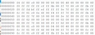
Thanks for your reply. We have tried again and read such register which is shown as below:
I think the register is correct, but it doesn't give any response.
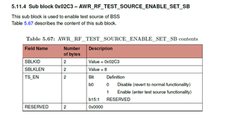
The configuration of the test source is shown below:
However, the captured ADC data is combined of CP value and raw ADC data in the format of RAW14. The CP value seems correct but the ADC raw data seems not correct. Most of the captured data are the minimum or the maximum.
As the test source is set open, the ADC data should not be affected by the RF module. is there any possible problem that makes the data wrong?
In addition, is it reliable for the thought that as the Cp data is correct, the transmission of the data (the configuration of the CSI2 datapath) is without error?
How are you capturing the data, is it with the AWR2243BOOST and DCA1000 or is it with a custom board? If there is an issue, it is either with the test source configuration or the CSI2 data capture, the test source does not use the RF front end.
We used our custom board and tried to capture ADC data and the chirp parameter data using CSI2. We found the chirp parameter data is correct with wrong ADC data with test source on.
Therefore, our questions are:
1. Is there any suggested monitors or some commands can be used for diagnosing the problem?
2. Could we get to the conclusion that the CSI2 data lane is w/o problems if we get the correct chirp parameter sent out?
3. Could you please help to verify the configuration of the test source as set in the last thread or is there any possible methods to verify that the configuration of the test source is correct?
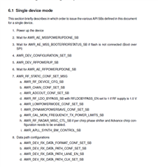
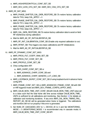
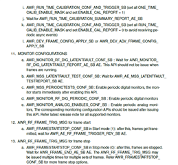
Can you please provide your sequence of mmwavelink API commands from start to end, similar to something like below?
We should first verify that you are following the correct API sequence. Once this is verified, then we will need to look further into how you are capturing and parsing the data.
Another thing you should check is that you are not exceeding the throughput of the CSI2 interface. You can calculate this like below:
Data rate required = (numADCSamples*numBitsPerSample*numRX)/(idleTime+RampEndTime)
Assuming 1024 samples, 16 bits per sample, 4 RX, 2uS idle time, 32.9us ramp end time
(1024*16*4)/(34.9*10^-6) = ~ 1878 Mbps
Max throughput = NumCSI2Lanes * CSI2DataRate
Assuming 600Mbps with four lanes, 600*4 = 2400 Mbps
Thanks, overall your sequence looks correct except I do not see the AWR_RF_TEST_SOURCE_CONFIG_SET_SB and AWR_RF_TEST_SOURCE_ENABLE_SET_SB being called. Are you calling these APIs and at which point are you calling them?
We are glad that worked out for you, and you are welcome for the assistance. Please do let us know, by posting a new thread, if something else comes up for you during your design development.