This thread has been locked.

If you have a related question, please click the "Ask a related question" button in the top right corner. The newly created question will be automatically linked to this question.

IWR6843AOP: Is there a limit to pin multiplexing

Part Number: IWR6843AOP

Hi TI Teams,

After we multiplexed the SPI pins into GPIOs when designing the IWR6843AOP, we found that the level could not be flipped and was always in high.

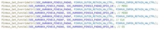
1) Pin multiplexing, which multiplexes SPI pins as normal GPIOs

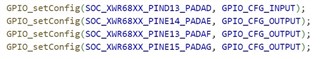
2) Pin configuration, configured for output mode

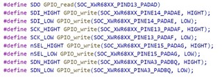
3) Pin High-Low Level Flip

So we are wondering is there a limit to pin multiplexing, or is there any mistake with using it this way? Can you help to confirm it?

Thanks,

Kind Regards

  • Hello

    If you look at the datasheet, you can see that you can use the SPIA pins as GPIO with no problem.

    Are you bit-banging SPI? It looks like a maybe based on those functions composed in the bottom image. If you are bit-banging, you should NOT be setting up or initializing the SPI driver in anyway. If you are attempting to use all 4 SPI pins as GPIO and you have also initialized the SPI driver, you will run into a problem where the SPI-state machine will not allow it (since SPI needs at least the CLK, a data line, and CS). You can see this in the TRM for SDK3 under SPI > "Using Unused SPI Pins as GPIO".

    If you are using the SPI driver and you want to use an unused data line as GPIO, you have to register with the SPI controller that you are wanting to use that line as GPIO in software.

    See this function implementation below which sets MOSI line to GPIO.

    // Tell the SPI driver MOSI will be GPIO
    ptrMibSpiReg->SPIPC0 = CSL_FINSR(ptrMibSpiReg->SPIPC0, SPIPC0_SIMOFUN_BIT_END, SPIPC0_SIMOFUN_BIT_START, 0U);
    ptrMibSpiReg->SPIPC0 = CSL_FINSR(ptrMibSpiReg->SPIPC0, SPIPC0_SIMOFUN0_BIT_END, SPIPC0_SIMOFUN0_BIT_START, 0U);
    
    // Set up pinmux for MOSI line as GPIO
    Pinmux_Set_OverrideCtrl(SOC_XWR68XX_PIND13_PADAD, PINMUX_OUTEN_RETAIN_HW_CTRL, PINMUX_INPEN_RETAIN_HW_CTRL);
    Pinmux_Set_FuncSel(SOC_XWR68XX_PIND13_PADAD, SOC_XWR68XX_PIND13_PADAD_GPIO_19);
    
    // Set the GPIO to be output
    GPIO_setConfig(SOC_XWR68XX_GPIO_19, GPIO_CFG_OUTPUT);
    
    GPIO_write(SOC_XWR68XX_GPIO_19, 0);

    Best Regards,

    Pedrhom

  • Hi Pedrhom,

    Thanks a lot. Now we have a new question about the FW, that is, does IWR6843AOP support to burn program to a external flash, and load program from external flash? If so, is there any information or documentation provided for this?

    Thanks,

    Kind Regards

  • Hello,

    By external flash do you mean flash variants for mmWave Sensors? If so we have a document covering this here:
    https://www.ti.com/lit/an/sprach9d/sprach9d.pdf?ts=1693583023605

    Best Regards,

    Pedrhom

  • Hello

    1. When I use IWR6843AOP's Uart to read data, data leakage is easy to occur. Is there an interrupt function on the Uart of 6843?

    2. As shown in the figure below, this is a cyclic read running in the Task, which is easily interrupted by other tasks, resulting in incorrect data read and inability to read AT instructions completely.

    3. Is there a better way to achieve it?

  • Hello,

    Could you start a new thread with an appropriate subject name and body name? To keep differing topics on different threads,

    Best Regards,

    Pedrhom