This thread has been locked.

If you have a related question, please click the "Ask a related question" button in the top right corner. The newly created question will be automatically linked to this question.

MMWCAS-RF-EVM: ESM Group 1 - FRC Lock Step Error

Part Number: MMWCAS-RF-EVM

I'm trying to use the MMWCAS-RF-EVM with an external clock and external trigger.  I've modified the resistors as indicated in the schematics: 

  • Use external trigger: uninstall 0 ohm from R143 and install 0 ohm on R142
  • Use external 40 MHz: uninstall  0 ohm from R121 and install 0 ohm on R116
  • Config AWR for single-ended clk: install 0 ohm on R128

If I configure and attempt to collect data using code modeled off the example code provided with the mmwave dfp library I get the following errror:

ESM Group 1 - FRC Lock Step Error

A couple additional things I've noticed about this behavior:

  • I only get this error with the master (AWR1), no errors are present with any of the slaves and I'm able to successfully collect data with them one at a time
  • If I put the master into software trigger mode, I do not get the error and am able to collect data

I've seen the errata regarding this error, but I don't think it's related because: A) my frame pulse is only 25ns and B) the external trigger works fine on all slave devices.

My AWRs are being configured via SPI in functional SOP mode.

Any ideas on why I'm getting the lock step error or any additional debugging I should do for more visibility into the problem?

Thanks.

  • Hello,

    It seems like there is some kind of timing error for the digital sync occurring. Please give me a day to look into this and get back to you by tomorrow.

    Regards,

    Adrian

  • Hello,

    Your hardware modifications look to be correct.

    Since you are using the EVM, can you try the same test in mmWave Studio to rule out any software issues?

    Regards,

    Adrian

  • Can mmWave Studio be used with an external trigger?  Is the TDA board capable of generating that?

  • Brandon - 

    How are you syncing HW trigger and the frame start API to the master device, can you describe or share image of your setup? 

  • I'm using custom hardware to interface with the MMWCAS-RF-EVM and the trigger is being generated on that hardware.  It is provided synchronous with the 40MHz that is also provided from the custom hardware.  The trigger only begins after the frame start API call is made.

    I also have the capability of running with the MMWCAS-RF-DSP, but I'm not sure if that can be used to generate external clock and trigger as I need.

    Unfortunately, I haven't been able to find any documentation on what the FRC error means, how I can possibly get additional debug information, etc. to work through what is causing this issue.  Any insights are appreciated.

  • Hello,

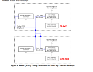
    I was thinking that there would be an SMA connector or something similar where the dig sync could be accessed on the host board, but I just checked the schematic and that does not seem to be the case. The dig sync is connected directly to the TDA processor, so using studio with hw trigger will not be possible unless you solder a wire to bring the dig sync out to a signal generator. 

    The FRC is used to maintain the timing across frames, so this error typically would indicate that there is some kind of issue with your external digital sync trigger timing.

    https://www.ti.com/lit/an/swra574b/swra574b.pdf

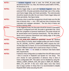
    Is it possible that your sync in pulse is sometimes below 25ns? Can you increase it to 30ns or so to add some margin? Also, is your hardware trigger timing meeting the requirements in note 4 below?

    Regards,

    Adrian