This thread has been locked.

If you have a related question, please click the "Ask a related question" button in the top right corner. The newly created question will be automatically linked to this question.

IWRL6432BOOST: Confusion regarding the mode of board while executing of demo examples available in MMWAVE_SDK

Part Number: IWRL6432BOOST

Hi,
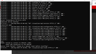
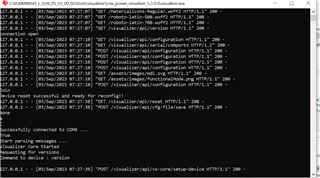
We were testing the examples available <MMWAVE_L_SDK_05_03_00_02/examples> on IWRL6432BOOST. We were using the functional mode to run the executable on the board. Is that correct or should need to run in debug mode?
And if it is in debug mode as suggested in below

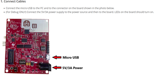
should we need  to use the power supply cable also.

One more doubt is that there is this document /cfs-file/__key/communityserver-discussions-components-files/1023/8132.xWRL6432_5F00_APL_5F00_CCS_5F00_debug_5F00_guide.pdf  explain the switch configuration for the debug mode. Is that correct? Becuase we were following https://www.ti.com/lit/ug/swru596/swru596.pdf?ts=1692856218712&ref_url=https%253A%252F%252Fwww.ti.com%252Ftool%252FIWRL6432BOOST this doc to set the mode. The switch configurations are different in both docs. Which one is correct???


Regards,
Sreekesh Giri

  • Hi Sreekesh, 

    Functional mode is correct. After the firmware is loaded to qspi flash (in Flashing mode) then switch to functional mode and sensor will boot from flash. 

    The process described in the first guide you linked is actually for running the demo from Code Composer Studio for debugging purposes (placing breakpoints, stepping through the code, etc...). In that case the demo does not boot from qspi flash but rather is connected via JTAG to CCS and the code is loaded directly to memory. This guide is also quite old and some of the links it references might be out of date and as such we will be removing it. An updated guide for debugging via CCS can be found here.

    I apologize for any confusion caused by these documents. Please let me know if you are facing any issues when flashing the demo code and running in functional mode or if you are just looking for clarification.

    Best Regards,

    Josh

  • Hi Josh, 

    So I was trying to run a mmwdemo from CCS. So the pin configuration to be used is functional mode as you told. But do we need to connect the power 5V/3A supply as shown in the figure?

  • Hello, 

    For running the demo in CCS functional mode is correct but you must have the 'empty.appimage' flashed on the board. Please see the guide I linked in my previous reply which describes this process. 

    But do we need to connect the power 5V/3A supply as shown in the figure?

    No, this should not be required. Most PCs should output enough power over USB so an additional power supply is not required. Are you experiencing any issues which you think may be related to insufficient power or are you just looking for confirmation? 

    Best Regards,

    Josh

  • Hi Josh,

    Thanks for the reply. For confirmation I asked. 

    So if we want to communicate to the board with CCS and sending config through Visualiser we would require JTAG connectivity as well? 

    Can you guide us on how to do this? 

    Thanks, 

    Remya

  • Hi Remya, 

    JTAG connection is handled through the on board XDS110. The only physical connection to the PC which is required is the USB. 

    we want to communicate to the board with CCS and sending config through Visualiser

    Please follow this guide (Using CCS Debug) to set up the demo in CCS. After completing section 3.3 then the configuration can be sent via the visualizer. The visualizer can be used normally. You can follow the steps in the Presence and Motion Detection User Guide to send the config. Instructions are provided for using either the SDK Visualizer or the Industrial Visualizer of the Radar Toolbox. 

    Best Regards,

    Josh

  • Hi Josh,

    As mentioned I was following the steps till 3.3 and opened visualiser for sending configuration. Then Iam getting this message. 

    In visualiser. 

    When I started the project build I have already done the reset and power cycling. 

    Can you please guide what sould be the next step?

    If I reset the board manually iam getting this on CCS 

    Cortex_M4_0: JTAG Communication Error: (Error -1170 @ 0x0) Unable to access the DAP. Reset the device, and retry the operation. If error persists, confirm configuration, power-cycle the board, and/or try more reliable JTAG settings (e.g. lower TCLK). (Emulation package 9.10.0.00080)

    visualiser not showing anything rather than this

  • Later I tried like before sending config through visualiser I manually resettted the device by pressing NRSTbutton and send the config file

    then iam getting like this

    and same JTAG communication error in CCS

  • Hi,

    It seems you are following the correct procedure. Please let me try to reproduce the same issue on my end and get back to you.

    Also, are you able to send the configuration using the Industrial Visualizer in the Radar Toolbox? Or does the issue only occur with the visualizer from the SDK?

    Regards, 

    Josh

  • Hi Josh, 

    when i connected the board using the CCS and loaded with my.out file and then later for sending config file iam opening the visualiser iam facing this issue. with industrial visualiser. 

    If iam not using ccs only connecting through industrial visualiser then this works fine

  • Hi, 

    Okay so the issue occurs with both visualizers when running the demo while connected in CCS and .out file is loaded. I am checking this on my end and will update you here by the end of the day. 

    Best Regards,

    Josh

  • Hi, 

    Very sorry for the delay here. I am still investigating this issue. Please allow me some additional time to find a solution. I will respond here Monday of next week. Your patience is greatly appreciated. 

    Best Regards,

    Josh

  • Hi, 

    Thank you very much for your patience. I have been able to reproduce the issue that you are seeing when you try this with the SDK Visualizer (Low_power_visualizer_5.3.0.0). I have reported the bug to our software team to try to identify a fix. 

    I have however been successful when using the Industrial Visualizer (from Radar Toolbox) as mentioned above. Please follow this guide (Using CCS Debug) to set up the demo in CCS. After completing section 3.3 then follow the steps in the Presence and Motion Detection User Guide (Starting from the section 4. Open the Radar Toolbox Industrial Visualizer ) to send the config. 

    Best Regards,

    Josh

  • Hi Josh,

    Thanks for the reply. I will check on my side and will update the observation here. 

  • No problem. Let me know if you are still facing issues. 

    Best Regards,

    Josh