This thread has been locked.

If you have a related question, please click the "Ask a related question" button in the top right corner. The newly created question will be automatically linked to this question.

AWR2243: There are no outputs on CLK and line for CSI interface

Part Number: AWR2243

Hi Team,

Follow the manual to configure AWR2243 via SPI and receive a response from Frame Trigger Ready and Frame end of RF_Async_event_MSG1 when FrameStart is enabled. But there are no signal outputs from CLK and line on CSI interface. 

The flow is as follows: 

1) Controls AWR2243 reset pin, waits for MSS_powerup_complete reply with a missing MetaHerer status.

2) The firmware array in the xwr22xx_metaImage.h file is loaded via SPI, and each packet is sent with an ACK reply, and there is no MSS_BOOTERRSTATUS reply as shown in the red box on the left of the figure below. The red box on the right side of the figure below tells you to wait for a 0x5005 event if no Flash is connected. Customer is currently designing to connect a flash via QSPI, will there be no response from MSS_BOOTERRSTATUS? How to determine if the firmware was loaded successfully after loading the firmware? 

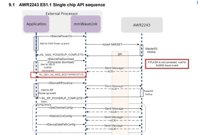
3) Enable RF PowerUp to receive the data replies: ba dc cd ab 36 a0 22 00 0c 00 00 00 01 00 9a 5f    01 50     14 00     fb fe 3b 07 76 50 21 00 10 00 00 00 00 00 00 00      20 61 

4) Configure Static_Conf_Set related register: 

a. AWR_RF_DEVICE_CFG_SB         configure ASYNC_EVENT_DIR为BSS TO HOST

Configure MONITORING_ASYNC_EVENT_DIR to BSS TO HOST 

Enable FRAME_START_ASYNC_EVENT and FRAME_STOP_ASYNC_EVENT

 Enable INTER_BURST_POWER_SAVE

Turn off WDT

Set ASYNC_EVENT_CRC to 32bit

b. AWR_CHAN_CONF_SET_SB     Enable 4-way RX and TX0

Configure to single Chip mode

Turn off FM_CW_CLKOUT_MASTER,   FM_CW_SYNCOUT_MASTER,  FM_CW_CLKOUT_SLAVE,  FM_CW_SYNCOUT_SLAVE,  INTLO_MASTER,   INTFRC_MASTER

Open OSCCLKOUT(which is used to source the external FPGA clock )

c. AWR_ADCOUT_CONF_SET_SB   configure adc to 12bit, Reduse Full Scale Bits is 0 and only real

d. AWR_RF_RADAR_MISC_CTL_SB    all configured to 0

5) DATA_PATH setting:

a. AWR_DEV_RX_DATA_FORMAT_CONF_SB  The data format for ADC is configured as needed 

b. AWR_DEV_RX_DATA_PATH_CONF_SET_SB  is configure to CSI interface mode

c. AWR_DEV_RX_DATA_PATH_CLK_SET_SB is configured to CLK_DDR mode and the rate is 150M

d. AWR_HIGHSPEEDINTFCLK_CONF_SET_SB is configured to 300M

e. AWR_DEV_CSI2_CFG_SET_SB: Per default Lane0 at Pos1, Lane1 at Pos2, Lane2 at Pos4, Lane3 at Pos5, CLK at Pos3, all wires are set to POL_plus; LineStartEnd is enabled 

6) Configure RF init, the data waiting to reply to RF_AE_INITCALIBSTATUS_SB is  ba dc cd ab 32 20 28 00 0c 04 00 00 01 00 98 db     04 10    18 00    fe 0f 00 80 fc 0f 00 00 23 00 00 00 3b 04 00 00 0f 00 00 00      c7 aa 9e 4d.

7) Configure Profile information and the sampling point is 64.

8) Configure CHIRP_CONF_set, bind Profile0, ChirpStartIndex and ChirpEndIndex are 0, set only 1 chirp 

9) Configure AWR_frame_CONF_SB, ChirpStartIndex and ChirpEndIndex are 0, NumLoops is 1 and NumFrames is 64 

10) Configure AWR_DEV_FRAME_CONF_SB,  NumChirps is 64 and HalfWordsPerChirp is 64(sampling point is 64 and transfer real only)

11) Enable FrameStart to receive Frame Trigger Ready for RF_Async_event_MSG1 and wait a while for a reply to the Frame end again 

Could you help check this case? Thanks.

Best Regards,

Cherry

  • Hello cherry,

    Is this with the AWr2243 with the DCA1000 EVM setup?
    Are you using a custom board?

    Regards,
    Saswat Kumar

  • Hi Saswat Kumar,

    Thank you for the support.

    Are you using a custom board?

    Yes, it's a custom board with version V1.1.

    Thanks and regards,

    Cherry

  • Hello Cherry,

    Was this verified with the AWR2243 EVM along with studio before finalizing this sequence?

    Regards,
    Saswat Kumar

  • Hi Saswat Kumar,

    Was this verified with the AWR2243 EVM along with studio before finalizing this sequence?

    No, this sequence is ported according to the official routine mmWaveLink_SingleChirp_example, and all configuration parameters are configured according to the txt file in the example.

    #
    #For detailed view of mmWave Radar configuration structure
    #please refer 
    #ti\control\mmwavelink\docs\doxygen\html\index.html
    #
    
    #
    #Global configuration
    #Advanced frame test enable/disable; 1 - Advanced frame; 0 - Legacy frame
    #Continuous mode test enable/disable; 1 - Enable; 0 - Disable
    #Dynamic chirp test enable/disable; 1 - Enable; 0 - Disable; This should not be enabled if Advanced chirp test is enabled
    #Dynamic profile test enable/disable; 1 - Enable; 0 - Disable
    #Advanced chirp test enable/disable; 1 - Enable; 0 - Disable; The legacy chirp API is not required if this is enabled
    #Firmware download enable/disable; 1 - Enable; 0 - Disable
    #mmWaveLink logging enable/disable; 1 - Enable; 0 - Disable
    #Calibration enable/disable; To perform calibration store/restore; 1 - Enable; 0 - Disable
    #Calibration Store/Restore; If CalibEnable = 1, then whether to store/restore; 1 - Store; 0 - Restore
    #Transport mode; 1 - I2C; 0 - SPI
    #Flash connected enable/disable; 1 - Enable; 0 - Disable
    #
    LinkAdvanceFrameTest=0;
    LinkContModeTest=0;
    LinkDynChirpTest=1;
    LinkDynProfileTest=0;
    LinkAdvChirpTest=0;
    EnableFwDownload=1;
    EnableMmwlLogging=0;
    CalibEnable=0;
    CalibStoreRestore=1;
    TransferMode=0;
    IsFlashConnected=1;
    #END
    
    #
    #power on master arguments, please modify if needed.
    #rlClientCbs_t: crcType 0:16Bit/1:32Bit/2:64Bit, ackTimeout
    #
    crcType=1;
    ackTimeout=1000;
    #END
    
    #
    #channel config parameters, please modify if needed.
    #rlChanCfg_t
    #
    channelTx=3;
    channelRx=15;
    cascading=0;
    #END
    
    #
    #ADC out config parameters, please modify if needed.
    #rlAdcOutCfg_t
    #
    adcBits=2;
    adcFormat=2;
    #END
    
    #
    #DATA format config parameters, please modify if needed.
    #rlDevDataFmtCfg_t
    #
    rxChanEn=15;
    adcBitsD=2;
    adcFmt=1;
    iqSwapSel=0;
    chInterleave=0;
    #END
    
    #
    #Low power config Paramters, please modify if needed.
    #rlLowPowerModeCfg_t
    #
    anaCfg=0;
    lpAdcMode=0;
    #END
    
    #
    #Data Path config parameters, please modify if needed
    #rlDevDataPathCfg_t
    #
    intfSel=1;
    transferFmtPkt0=1;
    transferFmtPkt1=0;
    cqConfig=2;
    cq0TransSize=64;
    cq1TransSize=64;
    cq2TransSize=64;
    #END
    
    #
    #LVDS clock config parameters, please modify if needed
    #rlDevDataPathClkCfg_t
    #
    laneClk=1;
    dataRate=1;
    #END
    
    #
    #SET HSI clock parameters, please modify if needed.
    #rlDevHsiClk_t
    #
    hsiClk=9
    #END
    
    #
    #LANE config parameters, please modify if needed.
    #rlDevLaneEnable_t
    #
    laneEn=15;
    #END
    
    #
    #LVDS Lane Config parameters, please modify if needed.
    #rlDevLvdsLaneCfg_t
    #
    laneFmtMap=0;
    laneParamCfg=1;
    #END
    
    #
    #Programmable Filter config parameters, please modify if needed.
    #rlRfProgFiltConf_t
    #
    profileId=0;
    coeffStartIdx=0;
    progFiltLen=14;
    progFiltFreqShift=100;
    #END
    
    #
    #Profile config parameters, please modify if needed.
    #rlProfileCfg_t
    #
    profileId=0;
    pfVcoSelect=2;
    startFreqConst=1439117143;
    idleTimeConst=1000;
    adcStartTimeConst=600;
    rampEndTime=6000;
    txOutPowerBackoffCode=0;
    txPhaseShifter=0;
    freqSlopeConst=621;
    txStartTime=0;
    numAdcSamples=256;
    digOutSampleRate=10000;
    hpfCornerFreq1=0;
    hpfCornerFreq2=0;
    rxGain=30;
    #END
    
    #
    #Profile config parameters, please modify if needed.
    #rlProfileCfg_t
    #
    profileId=1;
    pfVcoSelect=2;
    startFreqConst=1439117143;
    idleTimeConst=1000;
    adcStartTimeConst=700;
    rampEndTime=6000;
    txOutPowerBackoffCode=0;
    txPhaseShifter=0;
    freqSlopeConst=621;
    txStartTime=0;
    numAdcSamples=256;
    digOutSampleRate=10000;
    hpfCornerFreq1=0;
    hpfCornerFreq2=0;
    rxGain=30;
    #END
    
    #
    #Profile config parameters, please modify if needed.
    #rlProfileCfg_t
    #
    profileId=2;
    pfVcoSelect=2;
    startFreqConst=1439117143;
    idleTimeConst=1000;
    adcStartTimeConst=800;
    rampEndTime=6000;
    txOutPowerBackoffCode=0;
    txPhaseShifter=0;
    freqSlopeConst=621;
    txStartTime=0;
    numAdcSamples=256;
    digOutSampleRate=10000;
    hpfCornerFreq1=0;
    hpfCornerFreq2=0;
    rxGain=30;
    #END
    
    #
    #Profile config parameters, please modify if needed.
    #rlProfileCfg_t
    #
    profileId=3;
    pfVcoSelect=2;
    startFreqConst=1439117143;
    idleTimeConst=1000;
    adcStartTimeConst=900;
    rampEndTime=6000;
    txOutPowerBackoffCode=0;
    txPhaseShifter=0;
    freqSlopeConst=621;
    txStartTime=0;
    numAdcSamples=256;
    digOutSampleRate=10000;
    hpfCornerFreq1=0;
    hpfCornerFreq2=0;
    rxGain=30;
    #END
    
    #
    #Chirp Configuration parameters, please modify if needed.
    #rlChirpCfg_t
    #
    chirpStartIdx=0;
    chirpEndIdx=63;
    profileIdCPCFG=0;
    startFreqVar=0;
    freqSlopeVar=0;
    idleTimeVar=0;
    adcStartTimeVar=0;
    txEnable=1;
    #END
    
    #
    #Chirp Configuration parameters, please modify if needed.
    #rlChirpCfg_t
    #
    chirpStartIdx=64;
    chirpEndIdx=127;
    profileIdCPCFG=0;
    startFreqVar=0;
    freqSlopeVar=0;
    idleTimeVar=0;
    adcStartTimeVar=0;
    txEnable=2;
    #END
    
    #
    #Frame configuration parameters, please modify if needed.
    #rlFrameCfg_t
    #
    chirpStartIdxFCF=0;
    chirpEndIdxFCF=127;
    frameCount=50;
    loopCount=1;
    periodicity=20000000;
    triggerDelay=0;
    numAdcSamples=512;
    triggerSelect=1;
    #END
    
    #
    #Advance Frame configuration parameters, please modify if needed.
    numOfSubFrames=4;
    forceProfile=0;
    numFrames=100;
    loopBackCfg=0;
    triggerSelect=1;
    frameTrigDelay=0;
    #end
    
    #
    #4th sub Frame configuration parameters, please modify if needed.
    forceProfileIdx=0;
    chirpStartIdxAF=0;
    numOfChirps=1;
    numLoops=8;
    burstPeriodicity=5000000;
    chirpStartIdxOffset=0;
    numOfBurst=1;
    numOfBurstLoops=1;
    subFramePeriodicity=5000000;
    numAdcSamplesAF=256
    numChirpsInDataPacket=1
    #end
    
    #
    #3rd sub Frame configuration parameters, please modify if needed.
    forceProfileIdx=0;
    chirpStartIdxAF=0;
    numOfChirps=1;
    numLoops=8;
    burstPeriodicity=5000000;
    chirpStartIdxOffset=0;
    numOfBurst=1;
    numOfBurstLoops=1;
    subFramePeriodicity=5000000;
    numAdcSamplesAF=256
    numChirpsInDataPacket=1
    #end
    
    #
    #2nd sub Frame configuration parameters, please modify if needed.
    forceProfileIdx=0;
    chirpStartIdxAF=0;
    numOfChirps=1;
    numLoops=8;
    burstPeriodicity=5000000;
    chirpStartIdxOffset=0;
    numOfBurst=1;
    numOfBurstLoops=1;
    subFramePeriodicity=5000000;
    numAdcSamplesAF=256
    numChirpsInDataPacket=1
    #end
    
    #
    #1st sub Frame configuration parameters, please modify if needed.
    forceProfileIdx=0;
    chirpStartIdxAF=0;
    numOfChirps=1;
    numLoops=8;
    burstPeriodicity=5000000;
    chirpStartIdxOffset=0;
    numOfBurst=1;
    numOfBurstLoops=1;
    subFramePeriodicity=5000000;
    numAdcSamplesAF=256
    numChirpsInDataPacket=1
    #end
    
    #
    #Continuous mode config parameters
    #startFreqConst=1435384036;
    #txOutPowerBackoffCode=0;
    #txPhaseShifter=0;
    #digOutSampleRate=10000;
    #hpfCornerFreq1=0;
    #hpfCornerFreq2=0;
    contModeRxGain=30;
    vcoSelect=3388;
    #end
    
    #
    #Advanced chirp config parameters
    AdvChirp_chirpParamIdx=0;
    AdvChirp_resetMode=0;
    AdvChirp_deltaResetPeriod=0;
    AdvChirp_deltaParamUpdatePeriod=0;
    AdvChirp_sf0ChirpParamDelta=0;
    AdvChirp_sf1ChirpParamDelta=0;
    AdvChirp_sf2ChirpParamDelta=0;
    AdvChirp_sf3ChirpParamDelta=0;
    AdvChirp_lutResetPeriod=4;
    AdvChirp_lutParamUpdatePeriod=1;
    AdvChirp_lutPatternAddressOffset=0;
    AdvChirp_numPatterns=4;
    AdvChirp_lutBurstIndexOffset=0;
    AdvChirp_lutSfIndexOffset=0;
    AdvChirp_lutChirpParamSize=0;
    AdvChirp_lutChirpParamScale=0;
    AdvChirp_maxTxPhShifIntDither=0;
    #end
    
    #
    #Advanced chirp Profile config LUT parameters
    #Each data parameter is 4 bits
    AdvChirpLUT_ProfileConfig_LUTAddrOff=0;
    AdvChirpLUT_ProfileConfig_Data1=0;
    AdvChirpLUT_ProfileConfig_Data2=1;
    AdvChirpLUT_ProfileConfig_Data3=2;
    AdvChirpLUT_ProfileConfig_Data4=3;
    #end
    
    #
    #Advanced chirp Start Freq config LUT parameters
    #The Start Freq data is in GHz
    #Each data parameter is 1 or 2 or 4 bytes depending on ParamSize
    # ParamSize    Size in bytes
    #     0             4
    #     1             2
    #     2             1
    AdvChirpLUT_StartFreqConfig_LUTAddrOff=4;
    AdvChirpLUT_StartFreqConfig_ParamSize=1;
    AdvChirpLUT_StartFreqConfig_ParamScale=0;
    AdvChirpLUT_StartFreqConfig_Data1=-0.000001;
    AdvChirpLUT_StartFreqConfig_Data2=0.000000;
    AdvChirpLUT_StartFreqConfig_Data3=0.000001;
    AdvChirpLUT_StartFreqConfig_Data4=-0.000001;
    #end
    
    #
    #Advanced chirp Freq Slope config LUT parameters
    #The Freq Slope data is in MHz/us
    #Each data parameter is 1 byte
    AdvChirpLUT_FreqSlopeConfig_LUTAddrOff=12;
    AdvChirpLUT_FreqSlopeConfig_Data1=-0.050;
    AdvChirpLUT_FreqSlopeConfig_Data2=0.000;
    AdvChirpLUT_FreqSlopeConfig_Data3=-0.050;
    AdvChirpLUT_FreqSlopeConfig_Data4=0.050;
    #end
    
    #
    #Advanced chirp Idle time config LUT parameters
    #The Idle time data is in us
    #Each data parameter is 1 or 2 bytes depending on ParamSize
    # ParamSize    Size in bytes
    #     0             2
    #     1             1
    AdvChirpLUT_IdleTimeConfig_LUTAddrOff=16;
    AdvChirpLUT_IdleTimeConfig_ParamSize=0;
    AdvChirpLUT_IdleTimeConfig_ParamScale=0;
    AdvChirpLUT_IdleTimeConfig_Data1=0.01;
    AdvChirpLUT_IdleTimeConfig_Data2=0.02;
    AdvChirpLUT_IdleTimeConfig_Data3=0.00;
    AdvChirpLUT_IdleTimeConfig_Data4=0.01;
    #end
    
    #
    #Advanced chirp ADC time config LUT parameters
    #The ADC start time data is in us
    #Each data parameter is 1 or 2 bytes depending on ParamSize
    # ParamSize    Size in bytes
    #     0             2
    #     1             1
    AdvChirpLUT_ADCTimeConfig_LUTAddrOff=24;
    AdvChirpLUT_ADCTimeConfig_ParamSize=0;
    AdvChirpLUT_ADCTimeConfig_ParamScale=0;
    AdvChirpLUT_ADCTimeConfig_Data1=0.02;
    AdvChirpLUT_ADCTimeConfig_Data2=0.01;
    AdvChirpLUT_ADCTimeConfig_Data3=0.00;
    AdvChirpLUT_ADCTimeConfig_Data4=0.01;
    #end
    
    #
    #Advanced chirp Tx Enable config LUT parameters
    #Each data parameter is 4 bits
    #b0:TX0 ; b1:TX1; b2:TX2
    AdvChirpLUT_TxEnConfig_LUTAddrOff=32;
    AdvChirpLUT_TxEnConfig_Data1=7;
    AdvChirpLUT_TxEnConfig_Data2=3;
    AdvChirpLUT_TxEnConfig_Data3=1;
    AdvChirpLUT_TxEnConfig_Data4=2;
    #end
    
    #
    #Advanced chirp BPM Enable config LUT parameters
    #Each data parameter is 4 bits
    #b0:TX0 ; b1:TX1; b2:TX2
    AdvChirpLUT_BpmEnConfig_LUTAddrOff=36;
    AdvChirpLUT_BpmEnConfig_Data1=7;
    AdvChirpLUT_BpmEnConfig_Data2=3;
    AdvChirpLUT_BpmEnConfig_Data3=1;
    AdvChirpLUT_BpmEnConfig_Data4=2;
    #end
    
    #
    #Advanced chirp Tx0 Phase Shifter config LUT parameters
    #The phase shifter data is in degrees
    #Each data parameter is 1 byte
    AdvChirpLUT_Tx0PhShiftConfig_LUTAddrOff=40;
    AdvChirpLUT_Tx0PhShiftConfig_Data1=5.625;
    AdvChirpLUT_Tx0PhShiftConfig_Data2=11.250;
    AdvChirpLUT_Tx0PhShiftConfig_Data3=16.875;
    AdvChirpLUT_Tx0PhShiftConfig_Data4=16.875;
    #end
    
    #
    #Advanced chirp Tx1 Phase Shifter config LUT parameters
    #The phase shifter data is in degrees
    #Each data parameter is 1 byte
    AdvChirpLUT_Tx1PhShiftConfig_LUTAddrOff=44;
    AdvChirpLUT_Tx1PhShiftConfig_Data1=0.000;
    AdvChirpLUT_Tx1PhShiftConfig_Data2=5.625;
    AdvChirpLUT_Tx1PhShiftConfig_Data3=0.000;
    AdvChirpLUT_Tx1PhShiftConfig_Data4=5.625;
    #end
    
    #
    #Advanced chirp Tx2 Phase Shifter config LUT parameters
    #The phase shifter data is in degrees
    #Each data parameter is 1 byte
    AdvChirpLUT_Tx2PhShiftConfig_LUTAddrOff=48;
    AdvChirpLUT_Tx2PhShiftConfig_Data1=5.625;
    AdvChirpLUT_Tx2PhShiftConfig_Data2=0.000;
    AdvChirpLUT_Tx2PhShiftConfig_Data3=5.625;
    AdvChirpLUT_Tx2PhShiftConfig_Data4=0.000;
    #end

    Thanks and regards,

    Cherry

  • Hello Cherry,


    If ported according to the  mmWaveLink_SingleChirp_example then the config should be okay.
    As it is a custom board, have you verified whether the schematic for the CSI is functional?

    Regards,
    Saswat Kumar