This thread has been locked.

If you have a related question, please click the "Ask a related question" button in the top right corner. The newly created question will be automatically linked to this question.

AWR2944EVM: AWR2944 Evaluation Module PCB design files doesn't belong to current evaluation module

Part Number: AWR2944EVM

Hello TI team,

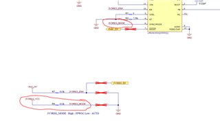
How can i reach recent pcb design documents of AWR2644EVM. There are some uncertain things to make evaluation module stable. Such as reset connections from LM63635DQDRRRQ1's RESET pin to LP877451A1RXVRQ1 PMIC's EN(enable) pin to disable PMIC when the output voltage of the LM63635DQDRRRQ1 is not good. So, if it is available, please change with old version or send me.

Best regards.

  • Hello,

    I do not fully understand your question. Can you please clarify your issue? What revision of the AWR2944EVM do you have?

    Regards,

    Adrian

  • i have aimed to say that please can you share current schematic and layout design documents for AWR2944EVM board.

    Thanks,

    Ismail

  • For example, in the schematic and layout design that i have has some uncertain connection types. Please take a look on the picture below. In there, we can observe that the SYNC/MODE pin of the LM63635DQDRRRQ1 IC has connected to both 3V3 regulator supply and gnd through the 10K resistors. However, according to datasheet fo the LM63635DQDRRRQ1, you should connect this pin VCC or AGND directly for fixed output mode. But the schematic wasn't designed according to this requirement. Propably, the engineer designed it for test(DFT). So, i need this document's current version. Those design files that you shared in AWR2944EVM's AWR2944EVM mustn't be current document. Because, most of ICs has still uncertain connection types as i mentioned.

    Thanks,

    Ismail

  • Hello,

    The SYNC is only connected to VCC, the resistor to GND is not populated. The schematic available on the AWR2944EVM page is exactly as it is in production. We have resistor options to enable different modes if the user wishes to change how these resistors are populated.

    https://www.ti.com/lit/zip/sprr440

  • Okay sir,

    thought that the documents has changed. I guess that TI designed this board as configurable. But actually, There wasn't any recommendation to connect SYNC/MODE pin to VCC by using resistor. Look at the picture below please. So, it might be wrong configuration because of 10K resistor. Datasheet doesn't recommend to use a resistor for this configuration. 

    As result, This documents that you shared is the last version, right?

  • Hello,

    It is common practice to use a pullup or pulldown resistor to limit the current into the IO pin. You can replace the 10k resistor with a 0 ohm resistor if you want, it will work either way. 

    Yes, the document provided is the latest revision.

    Regards,

    Adrian