This thread has been locked.

If you have a related question, please click the "Ask a related question" button in the top right corner. The newly created question will be automatically linked to this question.

AWR2944: Sensors forum

Part Number: AWR2944

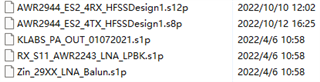
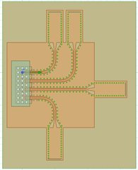
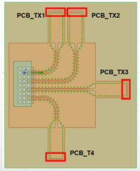
As a customer of the AWR 2944 chip, we received the chip EM model as below,

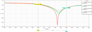
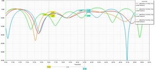
However, when we ran it in EM software without any modification, S11 at 76GHz is only -7 dB.

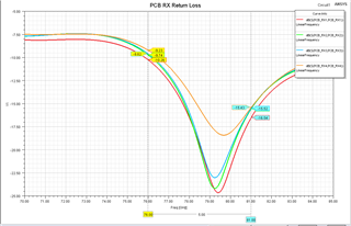
Besides, we cascaded this model with other well-matched transmission line models, the reflection is poor.

It needs to be mentioned that we did not do any modification on the chip model at all. Could we find the reason for this problem?

On the other hand, when in simulation, the message popped up, saying that, “while trying to update local material AUSSR1(/GHPL-830NS-LC/mold/NAU_27), the original library Materials was not found. The local material will be used.” Could this relate to the simulation problem?

Thanks a lot for your explanation.

  • Hi Yanheng,

    Are you running the Circuit model after you run HFSS mechanical simulation?  The mechanical model does not include the actual device complex impedance.  After you finish your mechanical based HFSS simulation you need to invoke the Circuit simulator and point the the SnP file from your HFSS simulation and also point to the given complex s1p device ports.  The model that we typically share has the Circuit model as an example.

    Regards,

    Sami

  • Hi Sami,

    Thank you very much for your detailed explanations.

    According to your suggestion, we ran the circuit model with the snp file from the EM results . Simulation results are as follows,


    The reflection is still poor.

    Besides, we repointed the default snp file you sent to us in the circuit model,as follows,


    Same result.

    Is there any software setting that we forgot or misused?

  • Hi Yanheng,

    Let me check on my end and I get back to you.

    Regards,

    Sami

  • Hi Yanheng,

    I would focus more on the PCB side than the DIE side:

    The plots above is from the PCB side and this is the side you need to match to.  It is a little bit marginal at 76 GHz but it should be ok.

    Regards,

    Sami

  • Hi Sami,

     Thanks a lot for your last reply. 

    According to your guidance and TI Radar PCB desgin guide, we simulated a simple test model based on the orginal one as below,

    The results of the circuit model from the PCB side are as below,

    We used simpe structure for the transmission lines in this test model, so that the casacade is fine. Nevertheless, we got the reflection plot above.

    Is this result acceptable? Or, is there any settings we forget to activiate? 

    We appreciate your reply. 

    Best Regards

    Yanheng

  • Hi Yanheng,

    No this is not good enough.  The recommendation is to stay below 10 dB in the band of interest and in the plot you referenced you are getting close to 5 dB.  Where is the reference port in you design?  I cannot see this in you attached drawing.

    Regards,

    Sami

  • Also are you using the same PCB stack material that we have in our reference design model files?  If not then you need to tune your PCB design to work with our HFSS model.

    Regards,

    Sami

  • Hi Sami,

    Thanks a lot for your last reply.

    The figure is redrawn with port number as below,

    Besides, the only thing we have modified is transmission line in the top layer. We didn't change any other things including the stack structure/material in the original model. 

    Regards,

    Yanheng

  • Hi Yanheng,

    Our impedance reference plane is defined close to the package edge.  From your drawing above I see that the port is far away from the package.  That extra structure you have needs to be matched to the package edge reference plane impedance.

    Regards,

    Sami