This thread has been locked.

If you have a related question, please click the "Ask a related question" button in the top right corner. The newly created question will be automatically linked to this question.

AWR1843BOOST: Programming custom Application - Minimal working example

Part Number: AWR1843BOOST
Other Parts Discussed in Thread: AWR1843, AWR1843AOP

Dear Customer-Service team,

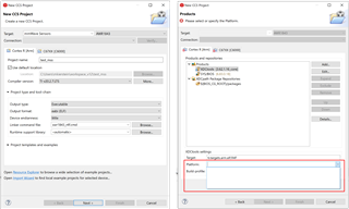
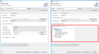
we want to develope our own radar applications from scratch. Is there a minimal working example we can use as a start? Unfortunately the answer of this thread: https://e2e.ti.com/support/tools/code-composer-studio-group/ccs/f/code-composer-studio-forum/836333/ccs-awr1843-1843 doesn't work for me. I dont see the option for the example project you mention there and the others don't seem to be sufficent to setup the project.

Thanks very much in advance.

Kind regards,

Mario  

  • Hi,

    It depends what your definition of "minimal" is.

    The AWR1843 sensor is a multi core device that includes several ARM cores, a DSP core and a Hardware accelerator.

    "Minimal" could mean as little as running a "hello world" example on the master ARM core.

    Please let us know what functionality is expected from the "minimal" example

    thank you

    Cesar

  • Hi Cesar,

    thanks very much for your response. 

    With "minimal" i mean just capturing the raw data as obtained from the receive antennas. The data should be already mixed with the transmitted chrip signal. But without any further signal processing. 

    Kind regards

    Mario 

  • Thank you for the additional information.

    We don't have such an example. The reason is that usually the unprocessed data rate is too high to be transferred out of the chip using UART.

    One can capture the raw data using a DCA1000 capture card.

    How did you plan to transfer the data out of the chip?

    thank you

    Cesar

  • Hi Cesar,

    thanks very much for your response. Using a DCA 1000 was our first attempt and will eventually be the way to go. However we have problems getting the card to work. The fpga seems to be broken. I have also posted a question regarding this matter. Unfortunately it hasnt been resolved yet + I didnt not get an answer since 5 days now. See https://e2e.ti.com/support/sensors-group/sensors/f/sensors-forum/1270824/dca1000evm-cannot-establish-ethernet-connection---fpga-not-found for more details.

    Our current attempt is to make a single snap-shot of the scene. Just like a picture. The total size of the data should be somewhere around 500kB I think. I belive,the total size of the RAM is 2048 kB. So we should be able to store the data of one snapshot, and transfer it to the PC via serial communication using CAN-FD, SPI or even UART.

    Do you see any problems with that attempt? Could you please do me the favor and check if anyone could please respond to my other qeustion mentioned above as well? 

    Thanks very much.

    Mario

  • Hi,

    Thank you for the additional information.

    Yes, this should work. However this will require some sw work. You will need to understand how the EDMA works to transfer the data from the ADC buffer to the L3 RAM.

    If you would like only to get a snapshot of the data, you can also save the radar cube data from the memory using CCS. This is the data after 1D fft.

    Then you can perform inverse fft in matlab and get the raw data after that if you wish.

    thank you

    Cesar

  • Hi Cesar,

    thanks very much for your reply. I think I will have to go with the first option: transferring the data from the ADC buffer to the L3 RAM.

    For me it is very important to get the raw, unprocessed data. I need it for the work in my phd-thesis. 

    Is there any additional information you can supply that can help me figuring out how to programm the software? Maybe you can also point me in the right direction by letting me know what steps I have to go through to capture the data and to get the data from the ADC to the L3 RAM.

    Thanks very much in advance,

    Mario 

  • Hi Cesar,

    maybe for a start it would be sufficient to work with the radar cube data after 1D fft. Could you please tell me how to access the data via CCS as you mentioned above. Are there any documented resources i could work with? Is there an easy way to send that data via USART (or other serial communication protocols) instead of using the CCS?

    Thanks in advance,

    Mario 

  • Hi

    I have found some old example that transfers raw data over uart. It is base on an old version of the mmWave SDK 2.x

    Unfortunately this is all the support we can provide on this.

    I think this path is very challenging because it requires you to become very familiar with the SW implementation and modify it.

    I recommend that you resolve the issue with the DCA1000 (replace if needed) and collect raw data using mmwave Studio tool

    Thank you
    Cesar

  • Hi Cesar,

    thanks for reply. 

    One more question. I am trying to create a new and empty project. Unfortunately the dropdown menu for the platform is empty. Do you know what might be the issue? I have tried to reinstall the SYS/BIOS as suggested in a diffrent thread. I also checked the release notes, the version of the XDC-tool and the SYS/BIOS should be compatibe, see screenshot below.

    Do you know what the problem might be?

    Kind regards,

    Mario 

  • Hi Cesar,

    would it be easier to access the radar cube data after 1D fft? Unfortunately the link you have sent me doesn't work.

    Regards,

    Mario

  • Please try the link again.

    In order to capture a radar cube after 1D fft you would need to use the emulator CCS.

    Unfortunately the AWR1843AOP EVM does not have an emulator on the board.

    You would need an additional board to use CCS. Do you have this board:

    https://www.ti.com/tool/MMWAVEICBOOST

    Thank you

    Cesar

  • Hi Cesar,

    thanks for your answer. No I dont have this board.

    Kind Regards

    Mario

  • In order to use CCS an emulator is required.

    Without CCS, it will be difficult to perform any software changes because there is no environment to debug.

    At this point the only option is to use a DCA1000 card to capture raw data

    thank you

    Cesar