


Team,
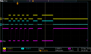
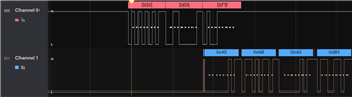
at the start the attached INIT sequence is sent, which should put the PGA460 into UART Mode: 0xF0, 0xF8, 0xFC:
The violet trace in the plots is what the PGA 'sees'. Due to the hardware set-up we have the TX/RX lines appear inverted
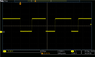
As a 2nd step I am cyclically sending the command 0x06, which the PGA460 should respond to with 2 Bytes of data: 0x55, 0x06 (Command 6), 0xF9 (Checksumme).
UART: 19200Bit/s, 2 Stop Bit, TX/RX inverse (due to the hardware set-up), 1 Start Bit
Could you please assist in the debugging, so I can get the communication with the PGA460 working.
Best regards
Frank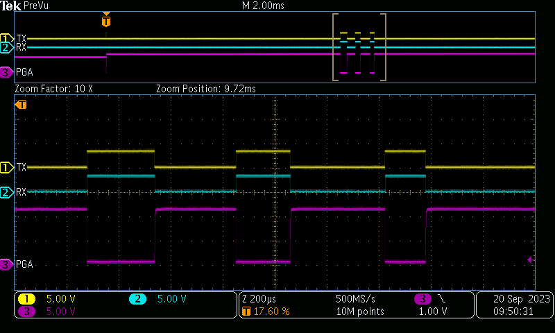


 egards,