This thread has been locked.

If you have a related question, please click the "Ask a related question" button in the top right corner. The newly created question will be automatically linked to this question.

TDC7200: Continuously measure the time difference between start/stop event and clock edge

Part Number: TDC7200
Other Parts Discussed in Thread: TDC7201

Hello,

I would like to use the TDC7200 (or an alternative chip that might be more suitable for my use case) to continuously measure the time difference between an event and the clock. With this, I would like to capture the exact time of randomly occurring edges. Since the clock is known and I can roughly place the signal in it, I just want to use the good time resolution of the TDC7200 to determine where exactly the edge occurred within a clock cycle.
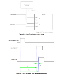
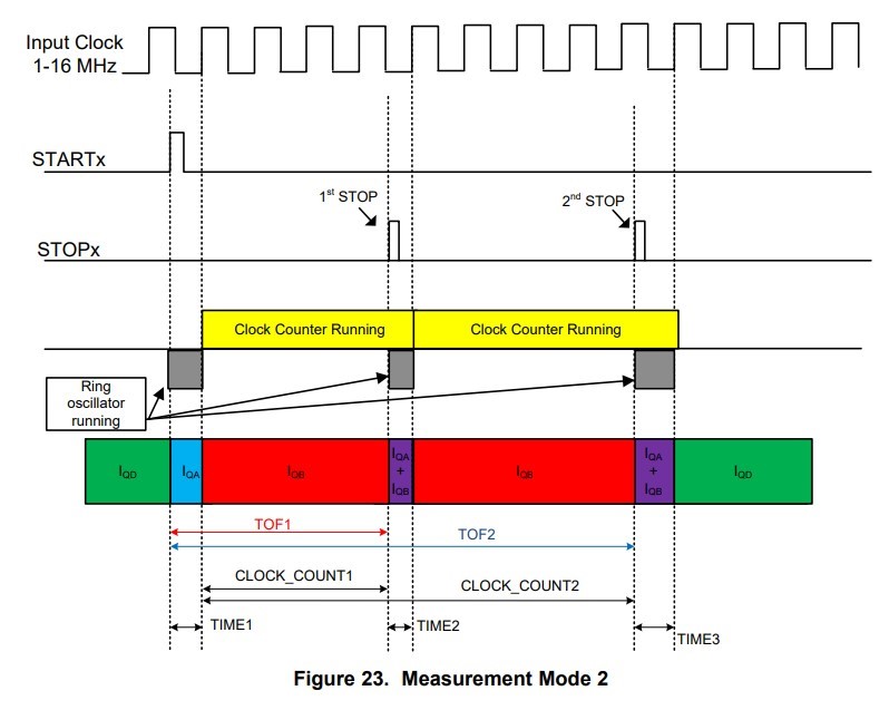
There is the Measurement Mode 2, where e.g. TIME1 is determined. This should be well suited to determine the difference between START and clock edge.
First question: Can a time shorter than 12 ns elapse between START and the clock edge?
Second question: I don't need a trigger from the microcontroller and even theoretically no stop signal. Is it possible to configure the chip in such a way that the TIME1 data can be acquired as quickly as possible after a START (and STOP) signal and that the chip is ready again very quickly for the next start signal?

Many thanks and best regards

  • Hello Silas,

    Thanks for posting to the sensors forum! Let me help address some of your questions and add some comments as well:

    1. A time shorter than 12ns is not possible with TDC7200, but this can measured with TDC7201 (two channel  version of TDC7200). Essentially both timers are connected to a reference START from an MCU. Your clock signal would provide the STOP pulse for one of the timers and your event signal would provide the STOP the other timer. You would have to read both sets of data and subtract the two results from each other. This will give you the timing difference between the event edge and the clock edge. I have included an image below of the TDC7201 datasheet for reference. The lidar signals here would be your clock and event signals.

    2. The Trigger is an output from the TDC7200, if this signal is not required for your system then it is not necessary to use. As far as a stop signal I believe you may be referring to the INTB pin. Which provides a signal to the MCU to let the microcontroller know when the data is ready to read the measurement. This signal is highly recommended if not borderline required. Reason being if your device performs a measurement and your MCU attempts to read the results from the TDC while the measurement is still being performed this will abort the measurement and if an event was detected and was read before the INTB pin indicates the data is ready the read will abort the measurement and the results will be cleared before they make it to the results register. In my experience the INTB pin can take up to 2us after a measurement is completed before it is asserted.

    If you are trying to collect small measurements my recommendation would be to use mode 1, as mode 2 is typically recommended for measurements 250ns - 8ms.

    I hope this helps!

    Best,

    Isaac


  • Hi Isaac,

    Thank you for the quick answer.
    So is it true that TIME1, that is the time between START and the next clock edge, cannot be less than 12 ns? Wouldn't that mean that if START is 11 ns before the clock edge, it is not detected at all or rounded up to 12 ns?

    BR Silas

  • Hello Silas,

    No worries, glad to help out! The 12ns requirement is the time from the START signal to the STOP signal for measurements in mode 1. The reason the clock is highlighted in the measurement 2 mode as pictured here is that the clock counter is used to measure larger intervals of time while the coarse counter (TIMEx registers) are used to count the smaller fragments of time this helps achieve a higher precision especially when an event occurs in between clock cycles. 

    If the intent is to use measurement mode 2 the minimum START to STOP measurement is dependent on the external clock frequency (2xt_clock). 

    Best,

    Isaac