This thread has been locked.

If you have a related question, please click the "Ask a related question" button in the top right corner. The newly created question will be automatically linked to this question.

AWRL1432: XYZ Coordinates and position interpolation in AoA DPU

Part Number: AWRL1432

Hi team,

I'm reading our docs in mmwave L sdk and I notice such 2 questions in our mmwave demo documentation:

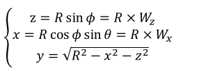
1. In our doc, we calculate x, y z in such ways

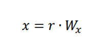
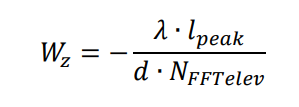
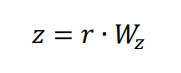
As we know, x=r*cos(Φ)*cos(θ), y=r*sin(Φ)*cos(θ), z=r*sin(θ), so, can you tell me why Wx=cos(Φ)*cos(θ) and Wz=sin(θ)?

2. In position interpolation, we use 2 formulas to calculate the bias

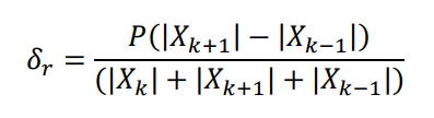
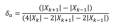
In the doc's reference, they say the formula2 is statistically biased and performs poor in noise. So why we still use it to calculate δa?

  • HI, there:

    When the antenna is 2D array, the phase difference between two antennas is defined as below.   

    In order to using 2D FFT approach to implement Bartlett beamforming, we have to define sin⁡θ cos⁡∅ as Wx and sin⁡∅ as Wz.   And then the x, y, z can be computed as below.

    For your second question, you should be able to disable the azimuth angle interpolation.  Customer can disable this feature if the performance is not beneficial and implement their own interpolation algorithm. 

    Best,

    Zigang

  • Hi Zigang,

    I know we need to realize beamforming, what I am confused about is why lambda*j(peak)/(d*N(FFTAzimuth))=cos(Phi)sin(Theta)? And the same question for Wz.

  • Hi, Shawn:

    If you looked at 2D FFT definition,

    you will see that you have to fit the phase change into two rotator Wm (in our case Wx), and Wn (in our case Wz).  One rotator can only be indexed by j (which can be mind in our case), and other one can only be indexed by k (which can be nind in our case).   

    Let me know if it is helpful.  

    Best,

    Zigang

  • Hi Zigang,

    I understand. Thank you!

    Regards,

    Shawn

  • Hello Shawn.

    I attach a simple slide to make the conversion from FFT grid into the Cartesian coordinates clear:

    I think the missing point in your equation is; FFT does not measure the φ and θ directly. It actually measures the μ and υ. SO a conversion is needed. Once you make this conversion according to the slide below, you will see that all the cos/sin computations are cancelled out and you will get the final value as noted in the SDK documentation.

    I hope this will make it clear.

    Regards.

    Muhammet

  • Hello Shawn.

    Regarding your second question, it is true. The formula 2 (which actually comes from a 3-pt parabola fit) may not perform perfect in the presence of noise. But this is the best option we could apply since we only have the magnitude of the range-angle heatmap in the memory.

    As you read the remaining sections of the same reference, you will see that we need to use the complex FFT values (i.e., complex heatmap) rather than the magnitudes to get a better performance. But it is not available in the current demo implementation. In terms of memory optimization, we did not store the complex heatmap only for interpolation.

    But, since the demo is just a baseline, you are welcome to improve the performance (if needed) with the other prosed options.

    Regards.

    Muhammet

  • Hi Muhammet,

    It's clear, I understand. It also explains my questions about the complex values in the reference doc, because I think we are processing real signal in 1432 signal chain.

    Regards,

    Shawn