This thread has been locked.

If you have a related question, please click the "Ask a related question" button in the top right corner. The newly created question will be automatically linked to this question.

AWR1843AOPEVM: How to debug using BOOST board

Part Number: AWR1843AOPEVM
Other Parts Discussed in Thread: AWR1843BOOST, , MMWAVEICBOOST, TMDSEMU110-U, AWR1843AOP

I wanted to debug my AWR1843AOPEVM board but in schematic as well as on board I couldn't find the emulator chip (XDS110) which was present on my AWR1843BOOST
But I could see a JTAG header on the board, can I use these pins to debug the board using the emulator present on my BOOST board if yes could you provide any reference document regarding how to do the same
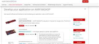
or do I need to use the 60pin HD connector to debug my AOP board and get some external debugger like MMWAVEICBOOST to debug the board.

Also what is the procedure to debug using XDS110 Debug Probe

 https://www.ti.com/tool/TMDSEMU110-U

Thanks 

  • Dear Tanoop - 

    Thanks for the post and welcome to E2E! 

    Connector J7 on the board has JTAG signals, as does connector J2. Pinout and image are shown in user manual for this EVM on pages 16 & 18. 

    https://www.ti.com/lit/ug/spruix8/spruix8.pdf 

    The JTAG port should work with any standard JTAG debugger that is compatible with the C674x DSP and ARM Cortex-R4F MCU. We have used the TMDSEMU110-U in the past without any issues.

    https://www.ti.com/tool/TMDSEMU110-U

    User guide is here: https://www.ti.com/lit/ug/sprui94/sprui94.pdf?ts=1697466288558&ref_url=https%253A%252F%252Fwww.ti.com%252Ftool%252FTMDSEMU110-U 

    Furthermore, another path, when using this EVM, is on our product page we put what is required here in the 'Develop your Application' Section, where you can find the explanation of usage for the MMWAVEICBOOST as part of your development hardware.   

    https://www.ti.com/tool/AWR1843AOPEVM#order-start-development 

  • Thanks for the response ,but in other thread I got the response  to debug using CCS I require MMWAVEICBOOST 
    e2e.ti.com/.../awr1843aopevm-xds110-debug

  • Tanoop - 

    Correct - using either standalone XDS110, the MMWAVEICBOOST or any other XDS110 based hardware (i.e. many of the Launchpads TI offers) for IEEE1149.1, IEEE1149.7, SWD based debugging should technically be an identical experience. 

  • I have purchased https://www.ti.com/tool/TMDSEMU110-Uc for dubugging my AWR1843AOP board.
    I have connected the Debugger through the DEBUG port on the debugger (CTI-20 connection ) and the JTAG header j7 on my awr1843aop board

    I hade already flashed the debug .bin file then also created a new .crxml file for debugging while testingthe cnnection getting success

    The library component version is '35.35.0.0'.
    The controller does not use a programmable FPGA.
    The controller has a version number of '5' (0x00000005).
    The controller has an insertion length of '0' (0x00000000).
    This utility will attempt to reset the controller.
    This utility has successfully reset the controller.

    -----[Print the reset-command hardware log-file]-----------------------------

    The scan-path will be reset by toggling the JTAG TRST signal.
    The controller is the XDS110 with USB interface.
    The link from controller to target is direct (without cable).
    The software is configured for XDS110 features.
    The controller cannot monitor the value on the EMU[0] pin.
    The controller cannot monitor the value on the EMU[1] pin.
    The controller cannot control the timing on output pins.
    The controller cannot control the timing on input pins.
    The scan-path link-delay has been set to exactly '0' (0x0000).

    -----[Perform the Integrity scan-test on the JTAG IR]------------------------

    This test will use blocks of 64 32-bit words.
    This test will be applied just once.

    Do a test using 0xFFFFFFFF.
    Scan tests: 1, skipped: 0, failed: 0
    Do a test using 0x00000000.
    Scan tests: 2, skipped: 0, failed: 0
    Do a test using 0xFE03E0E2.
    Scan tests: 3, skipped: 0, failed: 0
    Do a test using 0x01FC1F1D.
    Scan tests: 4, skipped: 0, failed: 0
    Do a test using 0x5533CCAA.
    Scan tests: 5, skipped: 0, failed: 0
    Do a test using 0xAACC3355.
    Scan tests: 6, skipped: 0, failed: 0
    All of the values were scanned correctly.

    The JTAG IR Integrity scan-test has succeeded.

    -----[Perform the Integrity scan-test on the JTAG DR]------------------------

    This test will use blocks of 64 32-bit words.
    This test will be applied just once.

    Do a test using 0xFFFFFFFF.
    Scan tests: 1, skipped: 0, failed: 0
    Do a test using 0x00000000.
    Scan tests: 2, skipped: 0, failed: 0
    Do a test using 0xFE03E0E2.
    Scan tests: 3, skipped: 0, failed: 0
    Do a test using 0x01FC1F1D.
    Scan tests: 4, skipped: 0, failed: 0
    Do a test using 0x5533CCAA.
    Scan tests: 5, skipped: 0, failed: 0
    Do a test using 0xAACC3355.
    Scan tests: 6, skipped: 0, failed: 0
    All of the values were scanned correctly.

    The JTAG DR Integrity scan-test has succeeded.

    [End: Texas Instruments XDS110 USB Debug Probe_0]


    but still getting this error while debugging or while connecting to the target

    Error connecting to the target:
    (Error -1170 @ 0x0)
    Unable to access the DAP. Reset the device, and retry the operation. If error persists, confirm configuration, power-cycle the board, and/or try more reliable JTAG settings (e.g. lower TCLK).
    (Emulation package 9.12.0.00150)

  • Tanoop - 

    Check table 2-9  (page20) for your SOP settings

    https://www.ti.com/lit/ug/spruix8/spruix8.pdf 

  • Hello Josh,

    Tested in all the modes ie. flashing, functional and MMWAVEICBOOST mode(JTAG) still getting the same error

  • Tanoop - 

    Please take a picture of your setup and/or provide diagram of how you connected everything. thanks!