This thread has been locked.

If you have a related question, please click the "Ask a related question" button in the top right corner. The newly created question will be automatically linked to this question.

AWRL1432BOOST: Antenna test and antenna calibration

Part Number: AWRL1432BOOST

Hi experts,

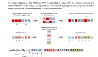
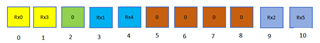
We are now using the custom antenna design in 1-D array, and here is the form link Configuration of custom antenna array, where I still have some issues about the azimuth FFT processing in the replies.

In addition, we have to do the antenna test and calibration. We also come cross some problems.

Q1: Using the custom antenna array in the above linked form, we need to do the antenna tests with only Tx0 or Tx1 enabled. I know the related configuration is channelCfg. But how should I configure the Txs to make all chirps are with Tx0 + Tx1 or Tx0 - Tx1, not BPM mode. In other words, how to configure all chirps with same phase pattern when enabling two Txs.

Q2: I notice the function mmwDemo_rangeBiasRxChPhaseMeasure() is used to do the antenna calibration. Is there and info about the function mmwDemo_factoryCal()? I am not sure if this is used for RF calibration?

Please also assist to address the issues in the above link, which now is blocking the progress! Thank you!

Kind regards

Liam

  • HI, Liam:

    Can you describe your plan for antenna test and calibration?  Are you plan to use DCA1000 capture board and mmWave Studio to get raw data? 

    Best,

    Zigang

  • Hi Zigang,

    There are four tests for antenna, let radar work with only Tx0, only Tx1, all chirps with Tx0 + Tx1 and all chirps with Tx0 - Tx1.  
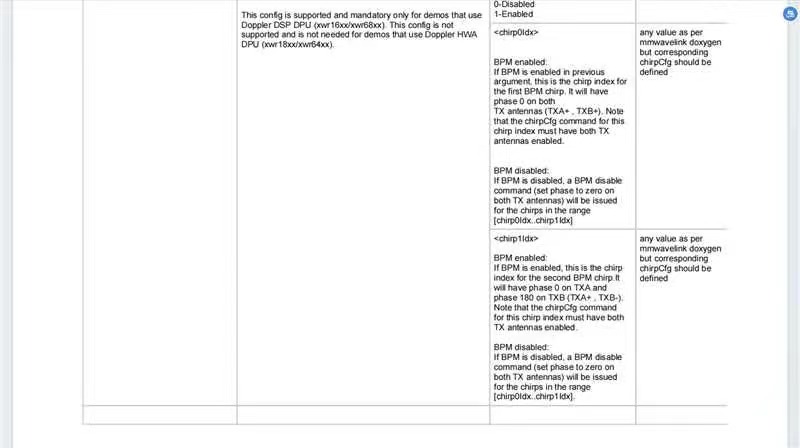
Here in 1843, I saw the parameter bpmCfg in which chirp0Idx and chirp1Idx could configure this.

    In terms of calibration, we do the compensation of all virtual antennas by the conner reflector in the function mmwDemo_rangeBiasRxChPhaseMeasure().

    At the current stage, we don't have to use DCA1000 to capture raw data, which I think to do next month. Besides, the problem unsolved is to insert the data to  the input array of azimuth FFT, in the link Custom antenna position. Broadly speaking, we have a custom antenna positon with 0 3 9, then I configureantGeometryCfg 0 0 0 4 0 9 0 1 0 5 0 10. If I need a input array of 64-point azimuth FFT like [Rx0, Rx3, 0, 0, Rx1, Rx4, 0, 0, 0, Rx2, Rx5, 0, 0, 0, 0,......,0], whether I should generate a custom dopplerParamCfg->dopFftCfg as the output of function MmwDemo_cfgDopplerParamMapping().

    Kind regards

    Liam

  • HI, Liam:

    Can you describe your application so that we can assign to the right team?

    Best,

    Zigang

  • Hi Zigang

    It's for autonomous driving with 1432.  

    I am using the mmwave_demo in the sdk example.

    Best regards

    Liam

  • Hi,

    Unfortunately we can only provide limited support for modifying the SDK demo.

    Our software development team is not able to support these questions

    thank you

    Cesar

  • Hi,

    Thank you for your apply

    It's been alreadly solved.

    Regards,

    Liam

  • Great to here that!

    thank you

    Cesar