This thread has been locked.

If you have a related question, please click the "Ask a related question" button in the top right corner. The newly created question will be automatically linked to this question.

OPT3101: How to calculate the value of the Matching Capacitor in the photodiode ?

Part Number: OPT3101

I am working on a hardware design with the OPT3101 module. Currently, the design has a high level of Illumination crosstalk around 150 codes of amplitude. I understand that the most convenient thing is to have a reading below 200 codes of amplitude, which is functional, but I want to reduce But this level of crosstalk, my point of comparison is the OPT3101EVM module that gives me 86 amplitude codes.

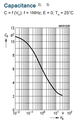
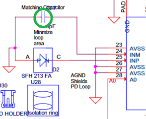
Change the value of the Matching capacitor from 6pF to 5.1pF, notice a reduction in the amplitude codes. I understand that this modifies the capacitance, but I would like to know how to choose the most appropriate value for the matching capacitor.

In general, if you have some extra recommendations to reduce Illumination crosstalk in my design, I clearly follow the recommendations in the SBAU305B, SBAS883A documentation.

If you need more details about my design I can send you my files for a better recommendation.

  • Garcia,

      The capacitance value for the matching capacitor comes from the data sheet of the SFH213FA. In the chart below you will notice that with a 0V bias we get 6pf of capacitance. 

    The sensor circuit is based on a differential measurement. That means that the capacitance of the IR detector must match the parallel capacitance in order to measure the current in the detector accurately. Yes changing the capacitance can lower your amplitude codes, but it does so by effecting the total accuracy and sensitivity of the circuit. 

    Try placing blackout tape on the sensors. They must be 100% blackouts to work. Multiple layers of black electrical tape will usually do the trick if you can get a good seal around and over the IR emitter and detector.  Then turn off the crosstalk calibration by unchecking the crosstalk illumination check boxes in Latte the registers. Then measure your amplitude codes. this is the real amplitude for the electrical crosstalk. Then remove the blackouts and read the amplitude codes. The difference between the two with and without the blackouts is the optical crosstalk. This will tell you where you need to work on the circuit for crosstalk.  Then turn back on the crosstalk variable check boxes to see how much the calibration can correct for the crosstalk. You can do this with and without the blackouts to see how much the optical crosstalk is left. You will probably see that the optical crosstalk is a small part of the total crosstalk unless the IR detector can directly see the IR emitter.

    Since the detector measures nano-amps it's easy to see electrical noise. A more robust RF layout of the circuit would probably help a lot. The EVM and module are well within the acceptable noise levels for evaluation and a better lower noise PCB will be up to you. We are working on a design guide to help lower the noise levels, but we are a ways away from having the data on that. Use good RF layout techniques, that will be the key. 

    Let me know if you have any more questions.

  • Varney,

    Thanks for the reply.
    Regarding the test you mention to measure electrical crosstalk, I performed the test with the SDK ported for my design, in the user guide it mentions that the IN_LAB_STEP_0 test is to validate the quality of the PCB design and layout and any optical or electrical shielding.

    I covered the photodiode with several layers of electrical tape and these are my results.

    My design

    OPT3101EVM

    From the result I understand that you have to pay attention to Amplitude and here the codes must be less than 30 to consider functional electrical crosstalk.

    Just some questions.
    What happens to the Magnitude variable that indicates exactly?

    What do you mean when you say, They must be 100% blackouts to work

  • Guillermo,

    The black outs must block IR Light. Sometimes something black or dark will not block IR.

    The Amplitude of the returned signal has little to do with distance. That would be DTOF (Direct Time of Flight) This is an ITOF (Indirect Time of Flight) That means the amplitude is used to determine the phase angle, which is used to calculate the distance. Good signal to noise ratio of the amplitude is important to get a more exact Phase angle. Magnitude is not important unless the signal is low and noisy preventing an accurate calculation. 

    Take the time to get the optical and electrical noise down and you will get more distance and accuracy. 

  • Hello Gordon

    Following your recommendation I will take the time to make some changes to reduce optical and electrical noise.
    For this I have some questions that I consider are a starting point for me.

    I appreciate each of your responses. I have new questions:

    1. I attach a picture of the stackup layer we have in our design. Our stacking layer is 0.8 mm due to the small footprint of our application. Do you consider this configuration to affect the optical and electrical crosstalk?We are using the following stackup layer configuration.

    This is the configuration recommended in IT reference designs.

    The solder mask used is black, as suggested in the guidelines.

    2. We supply voltage with a switched power supply to the OPT3101. The operating frequency is 2 MHz and 40mV Vpk-Vpk at a frequency of 100 KHz. Would you consider that we can decrease the crosstalk by adding a common mode filter and an LDO?

    3. Regarding recommendations for an RF design, we have done the following:

    a) Place stitching vias in the AGND and DGND planes to reduce the impedance in the planes.

    b) Terminate in ENIG terminals type 1u".

    c) The loops associated with the emitter (IR LED) and receiver (photodiode) are the same as those on the TI board.

  • Guillermo,

     Let me look over your questions and I will reply in the morning. 

  • Guillermo,

    Question:

    1) The stackup of the PCB is typically set to control impedances. In this case it will increase capacitance by bringing the ground plane closer to the top layer. That should not be bad for this design. 

    2) Any noise in the power rails can have an effect on noise in the circuit (Electrical crosstalk). Adding an LDO and filter is definitely good as the LDO will smooth out the ripple and increase PSRR. The additional parts come with a cost. That is a decision you need to make. 

    3) All of this sounds good.

    Note: keep the length of the traces for the receiver IR LED (INP, INM) as close to the same length as possible. This includes the ground side of the IR LED and the Capacitor. Treat them as a differential pair from the IC to the ground.