Other Parts Discussed in Thread: FDC2114EVM
Hi sir/mam,
We are using FDC2112 IC we are not understand that Sensor is in sleep mode or not in CKLIN pulse not coming and from SCL and SDA pulse is generating and from IN0A and IN0B pulse not coming.

This thread has been locked.
If you have a related question, please click the "Ask a related question" button in the top right corner. The newly created question will be automatically linked to this question.
Hi sir/mam,
We are using FDC2112 IC we are not understand that Sensor is in sleep mode or not in CKLIN pulse not coming and from SCL and SDA pulse is generating and from IN0A and IN0B pulse not coming.
Hello Sandhyarani,
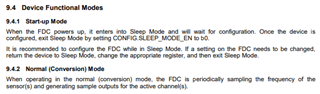
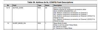
The device will power up in sleep mode and wait for configuration. We recommend configuring the device in sleep mode. After configuring the device, you can enter normal mode by setting CONFIG.SLEEP_MODE_EN to 0. You can also find more details in section 9.4 of the datasheet. Also, the SD pin should be low to be in active mode.

Hello sir,
This was our code
/**
Generated Main Source File
Company:
Microchip Technology Inc.
File Name:
main.c
Summary:
This is the main file generated using PIC10 / PIC12 / PIC16 / PIC18 MCUs
Description:
This header file provides implementations for driver APIs for all modules selected in the GUI.
Generation Information :
Product Revision : PIC10 / PIC12 / PIC16 / PIC18 MCUs - 1.81.8
Device : PIC18F25K80
Driver Version : 2.00
*/
/*
(c) 2018 Microchip Technology Inc. and its subsidiaries.
Subject to your compliance with these terms, you may use Microchip software and any
derivatives exclusively with Microchip products. It is your responsibility to comply with third party
license terms applicable to your use of third party software (including open source software) that
may accompany Microchip software.
THIS SOFTWARE IS SUPPLIED BY MICROCHIP "AS IS". NO WARRANTIES, WHETHER
EXPRESS, IMPLIED OR STATUTORY, APPLY TO THIS SOFTWARE, INCLUDING ANY
IMPLIED WARRANTIES OF NON-INFRINGEMENT, MERCHANTABILITY, AND FITNESS
FOR A PARTICULAR PURPOSE.
IN NO EVENT WILL MICROCHIP BE LIABLE FOR ANY INDIRECT, SPECIAL, PUNITIVE,
INCIDENTAL OR CONSEQUENTIAL LOSS, DAMAGE, COST OR EXPENSE OF ANY KIND
WHATSOEVER RELATED TO THE SOFTWARE, HOWEVER CAUSED, EVEN IF MICROCHIP
HAS BEEN ADVISED OF THE POSSIBILITY OR THE DAMAGES ARE FORESEEABLE. TO
THE FULLEST EXTENT ALLOWED BY LAW, MICROCHIP'S TOTAL LIABILITY ON ALL
CLAIMS IN ANY WAY RELATED TO THIS SOFTWARE WILL NOT EXCEED THE AMOUNT
OF FEES, IF ANY, THAT YOU HAVE PAID DIRECTLY TO MICROCHIP FOR THIS
SOFTWARE.
*/
#include "mcc_generated_files/mcc.h"
#include <htc.h>
#include<pic18f25k80.h>
#include<stdio.h>
#include<string.h>
#include<stdlib.h>
#define RW RC1
#define RS RC0
#define ENA RC2
#define Chck_Engine PORTBbits.RB0
#define I2C_SLAVE 0x2B // Slave device I2C address
#define Ref_Value 500
unsigned char i2cReadData = 0;
unsigned char l_address = 0;
unsigned long result,Avg,Avg_A,R,x,result_2,Result_3,result_1,result_1_Flt1,result_1_Pre,Pre_Result_1,X_Count;
unsigned long Fuel_pos = 0;
unsigned long Fuel_pos1 = 0;
unsigned long Fuel_pos2 = 0;
unsigned long Fuel_pos3 = 0;
unsigned char read_byte = 0;
unsigned char read_byte1 = 0;
unsigned char read_byte2 = 0;
unsigned char read_byte3 = 0;
unsigned int i = 0;
unsigned int Result_LSB;
unsigned char Avg_A_Higher,Avg_A_Lower;
unsigned int Count,Timer_Load;
unsigned char check,check_1;
unsigned long Fuel_Data_1,Fuel_Data_2,Fuel_Data_3,Fuel_Data_4;
unsigned int Height;
// unsigned int Value;
unsigned long Value,Value_1;
unsigned int MSec;
// unsigned long Buffer[100];
//olatile const unsigned int Freq_Table1[];
// unsigned int result;
// char read_byte[2];
extern unsigned char i2cReadData;
unsigned int toggle_variable = 0;
unsigned char Counter_1;
unsigned int X1,X2,X3,Y1,Y3,Y2;
unsigned int Full_Tank,Empty_Tank,Var_Count_1,Var_Count_2;
unsigned int Counts_5;
// volatile const unsigned int Fuel_Count_Table[98]={5370,5541,5775,6054,6325,6699,6935,7188,7511,7796,8020,8345,8617,8917,9186,9509,9770,10096,10367,10665,10920,11238,11479,11743,12027,12294,12534,12807,13028,13332,13596,13865,14068,14411,14670,14940,15215,15510,15765,16052,16283,16597,16810,17069,17343,17646,17912,18210,18485,18877,19054,19409,19682,20060,20365,20685,20995,21347,21610,21878,22104,22415,22650,22893,23127,23475,23704,23890,24107,24390,24602,24915,25131,25410,25699,25930,26185,26428,26692,26931,27163,27415,27583,27878,28143,28429,28653,28901,29108,29357,29590,29785,30347,30558,30819,30847,30876};
// volatile const unsigned int Fuel_Count_Table[98]={5326,5535,5825,6119,6430,6745,6991,7278,7588,7880,8191,8429,8779,9064,9324,9609,9871,10153,10443,10754,10923,11200,11509,11781,12033,12301,12547,12821,13092,13391,13674,13900,14192,14461,14739,14984,15273,15532,15786,16037,16309,16562,16834,17081,17439,17709,17944,18198,18640,18780,19104,19275,19772,20174,20550,20863,21096,21349,21677,21970,22204,22538,22688,22963,23207,23431,23666,23953,24203,24469,24731,24933,25170,25440,25638,25913,26125,26416,26651,26917,27129,27430,27672,27936,28120,28354,28633,28895,29112,29385,29583,29855,30222,30225,30282,30309,30350};
volatile const unsigned int Fuel_Count_Table[98]={110,247,384,521,658,795,932,1069,1206,1343,1480,1617,1754,1891,2028,2165,2302,2439,2576,2713,2850,2987,3124,3261,3398,3535,3672,3809,3946,4083,4220,4357,4494,4631,4768,4905,5042,5179,5316,5453,5590,5727,5864,6001,6138,6275,6412,6549,6686,6823,6960,7097,7234,7371,7508,7645,7782,7919,8056,8193,8330,8467,8604,8741,8878,9015,9152,9289,9426,9563,9700,9837,9974,10111,10248,10385,10522,10659,10796,10933,11070,11207,11344,11481,11618,11755,11892,12029,12166,12303,12440,12577,12714,12851,12988,13125};
volatile const unsigned int Height_Table[98] ={0,5,10,15,20,25,30,35,40,45,50,55,60,65,70,75,80,85,90,95,100,105,110,115,120,125,130,135,140,145,150,155,160,165,170,175,180,185,190,195,200,205,210,215,220,225,230,235,240,245,250,255,260,265,270,275,280,285,290,295,300,305,310,315,320,325,330,335,340,345,350,355,360,365,370,375,380,385,390,395,400,405,410,415,420,425,430,435,440,445,450,455,460,465,470,475,480};
unsigned int LSB_1,MSB_1;
unsigned int LSB_2,MSB_2;
unsigned char Message1[16],Message2[16],X,SampleFlag,AvgFlag;
unsigned int Fuel_Level,CanFuelLevel,CAN_Recieve_Data,MiliSecond,Second,CANModuleEr,CANBusEr;
unsigned int i,z;
unsigned long Read_Data[10];//,AverageOut[25];
unsigned long LSB,MSB,MSB1,LSB1;
unsigned char OdometerCount,OdoMeterFlag;
unsigned char temp,Display,SampleAvg,Display1;
unsigned long V1,V2,V3,V4,V5,V6,V7,V8,V9,V10;
long double Fuel_Economy_3;
unsigned long long Fuel_Economy,Fuel_Economy_1,Fuel_data,AvgFuel;
unsigned long long FuelEconomyFlag;
unsigned long buffer_Pre[26];
unsigned char s_count_Pre;
unsigned long long total_value_Pre;
unsigned char cnt_Pre;
unsigned long long avg_val_Pre;
unsigned int buffer[301];
unsigned char s_count,Done_Flag;
unsigned long long total_value;
unsigned int cnt;
unsigned long long avg_val;
unsigned long buffer_Flt1[201];
unsigned char s_count_Flt1;
unsigned long long total_value_Flt1;
unsigned char cnt_Flt1;
unsigned long long avg_val_Flt1;
unsigned int Holder[200];
void Initialize(void);
void LCD_Init(void);
void LCDDelay(unsigned int Delay);
void LCD_Display(void);
void CAN_Init(void);
//void Nibble_Send(unsigned char Send_Data);
#define I2C_WRITE 0
#define I2C_READ 1
void I2C_Init(const unsigned long c) {
SSPCON1 = 0x28; // Set the I2C master mode and enable the serial port
SSPCON2 = 0x00; // Clear control register 2
// SSPADD = (_XTAL_FREQ / (4 * c)) - 1; // Set the I2C clock speed
SSPADD = (40000000 / (4 * 100000)) - 1;
SSPSTAT = 0x00; // Clear status register
}
void i2c_Start() {
SEN = 1; // Send the start bit
while (!SSPIF); // Wait for the start bit to be sent
SSPIF = 0; // Clear the interrupt flag
}
void i2c_Restart(void){
RSEN = 1; // Send a repeated start bit
while (!SSPIF); // Wait for the repeated start bit to be sent
SSPIF = 0; // Clear the interrupt flag
}
void i2c_Stop() {
PEN = 1; // Send the stop bit
while (!SSPIF); // Wait for the stop bit to be sent
SSPIF = 0; // Clear the interrupt flag
}
void i2c_Write(unsigned char data) {
SSPBUF = data; // Write data to the buffer
while (!SSPIF); // Wait for the data to be sent
SSPIF = 0; // Clear the interrupt flag
}
unsigned char i2c_Read(unsigned char ack) {
RCEN = 1; // Enable reception
while (!SSPIF); // Wait for the data to be received
SSPIF = 0; // Clear the interrupt flag
if (ack) {
ACKDT = 0; // Acknowledge the data
} else {
ACKDT = 1; // Not acknowledging the data
}
ACKEN = 1; // Enable the acknowledge sequence
return SSPBUF; // Return received data
}
void i2c_Wait(void){
while ( ( SSPCON2 & 0x1F ) || ( SSPSTAT & 0x04 ) );
}
void i2c_Address(unsigned char address, unsigned char mode)
{
l_address=address<<1;
l_address+=mode;
i2c_Wait();
SSPBUF = l_address;
}
//unsigned char ECAN_Receive(void);
void delay(unsigned int value)
{
while(value-- != 0);
}
void i2c_FDC_command(unsigned char address, unsigned char command , unsigned char command1)
{
i2c_Start(); // send Start
i2c_Address(I2C_SLAVE, I2C_WRITE); // Send slave address - write operation
i2c_Write(address); // DATA WRITE
// i2c_Address(I2C_SLAVE, I2C_WRITE); // Send slave address - write operation
i2c_Write(command); // DATA WRITE
// i2c_Address(I2C_SLAVE, I2C_WRITE); // Send slave address - write operation
i2c_Write(command1); // DATA WRITE
i2c_Stop(); // send Stop
}
void CalculateCount(void)
{
Counter_1 = 97;
while (Counter_1 > 0)
{
if(result_1 >= (Fuel_Count_Table[Counter_1-1]) && (result_1 <= (Fuel_Count_Table[Counter_1])))
{
break;
}
Counter_1--;
X1 = Fuel_Count_Table[Counter_1-1];
X2 = result_1;
X3 = Fuel_Count_Table[Counter_1];
Y1 = Height_Table[Counter_1-1];
Y3 = Height_Table[Counter_1];
}
}
//// Send a command to ic
//void i2c_FDC_command(unsigned char address, unsigned char command)
//{
// i2c_Start(); // send Start
// i2c_Address(I2C_SLAVE, I2C_WRITE); // Send slave address - write operation
// i2c_Write(address); // DATA WRITE
// i2c_Write(command); // DATA WRITE
// i2c_Stop(); // send Stop
//}
// Read a char from ic
//unsigned char i2c_FDC_read(unsigned char address)
void i2c_FDC_read(unsigned char address)
{
// Read one byte
i2c_Start(); // send Start
i2c_Address(I2C_SLAVE, I2C_WRITE); // Send slave address - write operation
i2c_Write(address); // DATA WRITE
i2c_Restart(); // Restart
i2c_Address(I2C_SLAVE, I2C_READ); // Send slave address - read operation
read_byte = i2c_Read(1); // Read one byte
read_byte1 = i2c_Read(0);
// read_byte2 = i2c_Read(1);
// read_byte3 = i2c_Read(0);
// If more than one byte to be read, (0) should
// be on last byte only
// e.g.3 bytes= i2c_Read(1); i2c_Read(1); i2c_Read(0);
i2c_Stop(); // send Stop
}
void i2c_FDC_read_2(unsigned char address)
{
// Read one byte
i2c_Start(); // send Start
i2c_Address(I2C_SLAVE, I2C_WRITE); // Send slave address - write operation
i2c_Write(address); // DATA WRITE
i2c_Restart(); // Restart
i2c_Address(I2C_SLAVE, I2C_READ); // Send slave address - read operation
// read_byte = i2c_Read(1); // Read one byte
// read_byte1 = i2c_Read(1);
read_byte2 = i2c_Read(1);
read_byte3 = i2c_Read(0);
// If more than one byte to be read, (0) should
// be on last byte only
// e.g.3 bytes= i2c_Read(1); i2c_Read(1); i2c_Read(0);
i2c_Stop(); // send Stop
}
void Initialize()
{
OSCCON=0b01111111;
OSCCON2=0b00001000;
OSCTUNE=0b01000000;
ANCON0=0x00; // Analog @portA disabled
ANCON1=0x00;
ADCON0=0x00;
CM1CON=0x00;
CM2CON=0x00;
INTCON2=0x04; // PORTB Pull up depends on TRIS of corresponding Bit, Timer0 High Priority Interrupt
INTCON3=0x00;
HLVDCON=0x00;
CIOCON=0x00;
TXSTA1=0x00;
RCSTA1=0x00;
TXSTA2=0x00;
RCSTA2=0x00;
ODCON=0x00; // OPen Drain Disabled
TMR0L=224; // 1 MS Interrupt
TMR0H=0;
INTCON=0xE0; // GIE,PEIE,TMR0 Enabled, INT,RBINT Disabled
T0CON=0xC6; // TMR0 8 BIT, Prescalar 1:128
/* PMD0=0xfE;
PMD1=0b11111110; // TMR0 Module Enabled
PMD2=0b00001011;
LATA=0;
PORTA = 0;
TRISA = 0X00;
LATB=0;
PORTB = 0;
TRISB = 0X0F;
TRISCbits.TRISC7 = 1;
TRISCbits.TRISC6 = 0;
TRISCbits.TRISC5 = 0;
TRISBbits.TRISB5 = 0;
WPUB = 0xFF;*/
}
/*void CAN_Receive(void)
{
CANCON=0b11101000; // Configuration Mode
while(CANCONbits.REQOP<4);
ECANCON=0x00; // Mode 0 ,Legacy Mode
RXB0CON=0b00000000; // Receive only valid messages with standard identifier
// RXB1CON=0x00; // All Disabled
RXERRCNT=0x00;
// RXF0SIDH=0b11000111; //0b11001010; // Distance
// RXF0SIDL=0b11101010; //0b11000000;
// RXF0EIDH=0b11000001; //0x00; ////18FE563Dh
// RXF0EIDL=0b00000000; //0b00011111;
RXF0SIDH=0b11000111; // Distance
RXF0SIDL=0b11101011;
RXF0EIDH=0b00110000; // 18FF3012 ID
RXF0EIDL=0b00010010;
// TXB0SIDH=0b11000111; //
// TXB0SIDL=0b11101011;
// TXB0EIDH=0b00110000; // 18FF3012 ID
// TXB0EIDL=0b00010010;
RXM0SIDH=0xFF; // Mask Bits
RXM0SIDL=0xFF;
RXM0EIDH=0xFF;
RXM0EIDL=0xFF;
RXF1SIDH=0b11000111; //
RXF1SIDL=0b11101011;
RXF1EIDH=0b00110000; // 18FF3012 ID
RXF1EIDL=0b00010010;
// RXF1SIDH=0b11000111; //0b11001010; fuel economy // Filter Bits
// RXF1SIDL=0b11101010; //0b11000000;
// RXF1EIDH=0b11110010; //0x00; ////18FE563Dh
// RXF1EIDL=0b00000000; //0b00011111;
RXM1SIDH=0xFF; // Mask Bits
RXM1SIDL=0xFF;
RXM1EIDH=0xFF;
RXM1EIDL=0xFF;
BRGCON1=0b00000011; // BAUD RATE 250Kb/s SJW=1TQ
BRGCON2=0b10010000; // PS1=3TQ , PTS=1TQ
BRGCON3=0b00000010;
CIOCON=0b01110001; // oscillator as the source of the CAN system clock
RXB0DLC=0b00001000;
CANCON=0x00; // Normal Mode
while(CANCONbits.REQOP!=0);
TXERRCNT=0x00;
RXERRCNT=0x00;
CANSTAT=0b01101100;
PIR5=0x00;
PIE5=0b10100001;
IPR5=0xff;
RXB0CON=0b00000000;
PIR5=0x00;
}*/
/*void Nibble_seperat()
{
for(i=0;i<=3;i++) //3
{
temp=Display%10;
Display=Display/10;
temp=temp+48;
if(i==1)
{
i=2;
}
Message2[6-i]=temp; //6
Message2[5]=46;
}
}*/
/*void CAN_Transmit(void)
{
//+++++++++++++++++++++++++++++++++++++++++++++++++++++Transmission +++++++++++++++++++++++
CANCON=0b11101000;
while(CANCONbits.REQOP<4);
ECANCON=0x00;
TXB0CON=0b00000011; // TXREQ to be set at transmition
BRGCON1=0b00000011; // BAUD RATE 250Kb/s SJW=1TQ 0x84 0x81
BRGCON2=0b10010000; // PS1=3TQ , PTS=1TQ 0xb8 0xb8
BRGCON3=0b00000010;
CIOCON=0b11100001;
CANCON=0b00001000;
while(CANCONbits.REQOP!=0);
TXERRCNT=0x00;
RXERRCNT=0x00;
PIR5=0x00;
PIE5=0b10100100;
IPR5=0xff;
TXB0CONbits.TXREQ = 0;
// TXB0SIDH=0b11000111; //
// TXB0SIDL=0b11101010;
// TXB0EIDH=0b11110010; // 18FEF200 ID
// TXB0EIDL=0b00000000;
TXB0SIDH=0b11000111; //
TXB0SIDL=0b11101011;
TXB0EIDH=0b00110000; // 18FF3012 ID
TXB0EIDL=0b00010010;
//TXB0DLCbits.DLC = 1;
TXB0DLC = 0b00001000;
TXB0D4=1;
TXB0D5=0;
TXB0D6=1;
TXB0D7=0;
TXB0CONbits.TXREQ = 1;
PIR5=0x00;
}*/
void LCD_Display()
{
unsigned char LCD_Count;
// LCD Line 1
for(LCD_Count=0; LCD_Count<16; LCD_Count++)
{
EUSART2_Write(Message1[LCD_Count]);
}
for(LCD_Count=0; LCD_Count<16; LCD_Count++)
{
EUSART2_Write(Message2[LCD_Count]);
}
}
void UART1_uitoa(unsigned int number, char* ascii_number)
{
unsigned int position=0;
unsigned int length=0 ;
unsigned int temp_int=number;
if (number==0)
{
*( ascii_number)='0';
*( ascii_number+1)='\0';
}
else
{
while (temp_int)
{
temp_int/=10;
length++;
}
for (position=length;position>0;position--)
{
*( ascii_number + position-1) = '0' + number % 10;
number /= 10;
}
*( ascii_number + length) = '\0';
}
}
void SendStringSerially(const unsigned char* st)
{
while(*st)
EUSART2_Write(*st++);
}
void UART1_put_int(unsigned int number)
{
char ascii_number[ 11 ];
UART1_uitoa( number, ascii_number ) ;
SendStringSerially( ascii_number ) ;
}
int main()
{
unsigned int i;
CANModuleEr=0;
CANBusEr=0;
TRISC3 = 1; // SDA pin as input
TRISC4 = 1; // SCL pin as input
I2C_Init(100000);
SYSTEM_Initialize();
//CAN_Receive();
//CAN_Transmit();
// i2c_Init(); // Start I2C as Master 100KHz
strcpy(Message1," I2c initialized ");
delay(1000);
i2c_FDC_command(0x1A,0x00,0x00); //single channel configure
i2c_FDC_command(0x08,0x83,0x29); //CONVERSION TIME 6.66ms(100SPS)
i2c_FDC_command(0x09,0x83,0x29); //CONVERSION TIME 6.66ms(100SPS)
i2c_FDC_command(0x0A,0x83,0x29); //CONVERSION TIME 6.66ms(100SPS)
i2c_FDC_command(0x10,0x00,0x0A); //Settling time for channel zero
i2c_FDC_command(0x11,0x00,0x0A); //Settling time for channel zero
i2c_FDC_command(0x12,0x00,0x0A); //Settling time for channel zero
i2c_FDC_command(0x14,0x20,0x02); //To set drive for channel 0
i2c_FDC_command(0x15,0x20,0x02); //To set drive for channel 0
i2c_FDC_command(0x16,0x20,0x02); //To set drive for channel 0
i2c_FDC_command(0x19,0x00,0x00); //CONVERSION TIME 6.66ms(100SPS)
i2c_FDC_command(0x1B,0x02,0x0C); //C20D //MUX_CONFIG
// i2c_FDC_command(0x1E,0x7C,0x00); //Sensor drive current
i2c_FDC_command(0x1E,0x78,0x00); //Sensor drive current
i2c_FDC_command(0x1F,0x7C,0x00); //Sensor drive current
i2c_FDC_command(0x20,0x7C,0x00); //Sensor drive current
// i2c_FDC_command(0x1A,0x16,0x01); //CONFIG WITH SLEEP Disable external OSC
i2c_FDC_command(0x1A,0x14,0x01); //CONFIG WITH SLEEP Disable Internal OSC
// i2c_FDC_command(0x14,0x20,0x01); //To set drive for channel 0
strcpy(Message1," I2c Configuration ");
//LCD_Init();
strcpy(Message1," M.T.B.L. ");
strcpy(Message2," R.D.E.P.L ");
LCD_Display();
for(i=0;i<65500;i++);
for(i=0;i<65500;i++);
for(i=0;i<65500;i++);
for(i=0;i<65500;i++);
for(i=0;i<65500;i++);
for(i=0;i<65500;i++);
Fuel_Economy=0;
z=0;
X=20;
SampleFlag=0;
AvgFlag=1;
FuelEconomyFlag=1;
RC5 = 0;
RB5 = 0x00;
Done_Flag = 1;
while(1)
{
SendStringSerially("hello\n \r");
i2c_FDC_read(0x00);
SendStringSerially(" I2c data Read Byte 0:");//READ SINGLE FROM MSB
Fuel_pos = read_byte;//*1.27; MSB
UART1_put_int(Fuel_pos);
SendStringSerially("\t");
Fuel_pos1 = read_byte1;//*1.27;LSB
UART1_put_int(Fuel_pos1);
SendStringSerially("\n\r");
NOP();
i2c_FDC_read_2(0x01);
SendStringSerially(" I2c data Read Byte 1:");//READ SINGLE FROM MSB//READ SINGLE FROM LSB
Fuel_pos2 = read_byte2;//*1.27; MSB
UART1_put_int(Fuel_pos2);
SendStringSerially("\t");
Fuel_pos3 = read_byte3;//*1.27; LSB
UART1_put_int(Fuel_pos3);
SendStringSerially("\n\r");
Fuel_Data_4 = Fuel_pos3;
Fuel_Data_3 = Fuel_pos2;
Fuel_Data_2 = Fuel_pos1;
Fuel_Data_1 = Fuel_pos;
result = ((Fuel_Data_1<<24)|(Fuel_Data_2<<16)|(Fuel_Data_3<<8)|Fuel_Data_4);
MSec = 0;
SendStringSerially(" Result:");
UART1_put_int(result);
SendStringSerially("\n\r");
// while(MSec<36);
// LCDDelay(7550);
// LCDDelay(60000);
// LCDDelay(60000);
// LCDDelay(60000);
// LCDDelay(60000);
// LCDDelay(60000);
// Value_1 = (result)/1000;
Value = (result)/1000;
//300 counts running Avrage
buffer[0]=Value;
for(cnt=0;cnt<300;cnt++) //75s_count>=60
{
buffer[cnt+1] = buffer[cnt] ;
}
for(cnt=0;cnt<300;cnt++) //75s_count>=60
{
total_value += buffer[cnt];
}
avg_val_Flt1 = total_value/300; //75s_count>=60
result_1 = avg_val_Flt1; // Final Result
total_value = 0;
if(result_1 > 26544) // To control the max count coming form sensor
{ SendStringSerially(" Result Max:");
UART1_put_int(result_1);
SendStringSerially("\n\r");
//result_1 = 26544;
}
else if(result_1 < 24792) // To control the min count coming form sensor
{
SendStringSerially(" Result Min:");
UART1_put_int(result_1);
SendStringSerially("\n\r");
// result_1 = 24792;
}
Height = ((26544 - result_1)*50)/219; //138
Counts_5 = 26544 - result_1;
AvgFuel=Fuel_Economy_1/FuelEconomyFlag;
Display1 = AvgFuel;
SendStringSerially(" Avg Fuel:");
UART1_put_int(Display1);
SendStringSerially("\n\r");
if(CANModuleEr==0 && CANBusEr==0)
{
strcpy(Message1," Fuel Economy ");
strcpy(Message2," km/L ");
if(OdoMeterFlag==1)
{
AvgFuel=Fuel_Economy_1/FuelEconomyFlag;
Display1 = AvgFuel;
SendStringSerially(" Avg Fuel:");
UART1_put_int(Display1);
SendStringSerially("\n\r");
OdoMeterFlag=0;
FuelEconomyFlag=1;
Fuel_Economy_1=0;
// Display=Display1;
// Nibble_seperat();
}
//Display1=Fuel_Economy_3;
Display=Display1;
//Nibble_seperat();
}
/*else
{
if(CANBusEr==1)
{
strcpy(Message1," ERROR ");
strcpy(Message2," CAN BUS ");
}
else
{
strcpy(Message1," ERROR ");
strcpy(Message2," CAN MODULE ");
}
}
//LCD_Display();
}
}*/
/*void interrupt_isr(void)
{
if(TMR0IF==1)
{
MiliSecond++;
MSec++;
if(MiliSecond>=2000)
{
//---------------------Transmission---------------------------------------------//
// if(result<26485000)
// result = ((Fuel_Data_1<<24)|(Fuel_Data_2<<16)|(Fuel_Data_3<<8)|Fuel_Data_4);
//Height = (29008320-result)/4865; //4543; 26485000 //28260578 //2775551326341064
//Height = (result_1-5370)/54;
// CalculateCount();
// if(result_1>=110 && result_1<=13125)
// {
// Height = (((X2-X1)*(Y3-Y1))/(X3-X1))+Y1;
// LSB = (Height & 0xFF);
// MSB = ((Height & 0xFF00)>>8);
// }
//
// if(result_1<110)
// {
// Height = 0;
// }
// if(result_1>13125)
// {
// Height = 480;
// }
LSB = (Height & 0xFF);
MSB = ((Height & 0xFF00)>>8);
// Value =(29199999-result)/100; //29755739
LSB_1 = (result_1 & 0xFF);
MSB_1 = ((result_1 & 0xFF00)>>8);
LSB_2 = (Counts_5 & 0xFF);
MSB_2 = ((Counts_5 & 0xFF00)>>8);
// result_1 = ((MSB_1<<8)|LSB_1);
Second++;
TXB0CONbits.TXREQ = 0;
TXB0SIDH=0b11000111; //
TXB0SIDL=0b11101011;
TXB0EIDH=0b00110000; // 18FF3012 ID
TXB0EIDL=0b00010010;
// TXB0D0= Fuel_pos; //IBM Big Endian
// TXB0D1= Fuel_pos1;
// TXB0D2= Fuel_pos2;
// TXB0D3= Fuel_pos3;
// TXB0D0= Fuel_pos3; //Intel Little Endian
// TXB0D1= Fuel_pos2;
// TXB0D2= Fuel_pos1;
// TXB0D3= Fuel_pos;
TXB0D0= LSB_1; //result_1 LSB; //Intel Little Endian
TXB0D1= MSB_1; //result_1 MSB;
TXB0D2= LSB_2; //Counts_5 LSB
TXB0D3= MSB_2; //Counts_5 MSB
TXB0D4= LSB; //Height LSB
TXB0D5= MSB; //Height MSB
TXB0D6= 00;
TXB0D7= 00;
TXB0CONbits.TXREQ = 1;
MiliSecond = 0;
//---------------------Transmission---------------------------------------------//
//---------------------Rx---------------------------------------------//
// result = ((Read_Data[0]<<24)|(Read_Data[1]<<16)|(Read_Data[2]<<8)|Read_Data[3]);
// Height = Read_Data[5]<<8|Read_Data[4];
// MiliSecond = 0;
//---------------------Rx---------------------------------------------//
}
TMR0IF=0;
TMR0IE=1;
TMR0L=224;
TMR0H=0;
}
if(RXB0IF==1)
{
CANModuleEr=0;
CANBusEr=0;
Read_Data[0] = RXB0D0; //Byte1 Byte1 Fuel Rate LSB
Read_Data[1] = RXB0D1; //Byte2 Byte1 Fuel Rate MSB
Read_Data[2] = RXB0D2; //Byte1 Instantaneoue Fuel Economy LSB} WANTED
Read_Data[3] = RXB0D3; //Byte1 Instantaneoue Fuel Economy MSB} WANTED
Read_Data[4] = RXB0D4; //Byte1
Read_Data[5] = RXB0D5; //Byte1
Read_Data[6] = RXB0D6; //Byte1
Read_Data[7] = RXB0D7; //Byte1
//MSB = (Read_Data[3] << 8);
//LSB = (Read_Data[2] & 0x00FF);
//Fuel_Economy = (MSB|LSB);
RXB0CONbits.RXFUL=0;
RXB0IF=0;
PIE5bits.RXB0IE=1;
}
if(ERRIF==1)
{
CANModuleEr=1;
RXERRCNT=0x00;
TXERRCNT=0x00;
ERRIF=0;
}
if(TXB0IF==1)
{
CANModuleEr=0;
CANBusEr=0;
// Read_Data[0]=TXB0D0; //Byte1 Fuel Rate LSB
// Read_Data[1]=TXB0D1; //Byte2 Fuel RAte MSB
// Read_Data[2]=TXB0D2; //Byte3 Instantaneoue Fuel Economy LSB} WANTED
// Read_Data[3]=TXB0D3; //Byte4 Instantaneoue Fuel Economy MSB}
Read_Data[4]=TXB0D4; //Byte5
Read_Data[5]=TXB0D5; //Byte6
Read_Data[6]=TXB0D6; //Byte7
Read_Data[7]=TXB0D7; //Byte8
// MSB=(Read_Data[3]<<8); //1111101000000000
// LSB = (Read_Data[2] & 0x00FF); //11111010 194
// Fuel_Economy = MSB|LSB;
TXB0IF=0;
}
if(IRXIF==1)
{
CANBusEr=1;
IRXIF=0;
}*/
}
}
In this can you say where I need activate the sensor.In our point Sensor is not sensing where the issue we are facing we didnot understood.
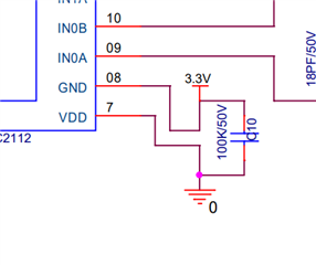
Here is my Schematic

The FDC2112 should be configured after power up. After the configuration, set CONFIG.SLEEP_MODE_EN to 0.
Hello sir,
In this code where I need to initiliaze CONFIG.SLEEP_MODE_EN to 0 this and I am not understand after powerup how can we configured we upload the code and we will ON the powersupply this is the process we will do . Can you highlight in code. And is my code is correct for sensing I2C
And Can you provide Fuel level sensor code based on my schematic previously I shared PIC18F25K80 is the controller and FDC2112 is the I2C.
And In FDC2112 SD 0v is generated but from SCL and SDA pulse generated but in IN0A and IN0B pulse not generated and 0v is generating.
Here I am attaching SCL and SDA generated pulse 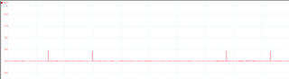

You should exit sleep mode after your configuration that is shown below. In your code, you are configuring register 0x1A with 0x14, 0x01, which is setting sleep mode EN to 0, but then you are setting the drive for channel 0 after. Disabling sleep mode should be the last register write of the configuration, although this does not explain why you see no signal. We do not have code for the PIC18F25K80, but do have some MSP430 C code that you can reference below.
// i2c_Init(); // Start I2C as Master 100KHz
strcpy(Message1," I2c initialized ");
delay(1000);
i2c_FDC_command(0x1A,0x00,0x00); //single channel configure
i2c_FDC_command(0x08,0x83,0x29); //CONVERSION TIME 6.66ms(100SPS)
i2c_FDC_command(0x09,0x83,0x29); //CONVERSION TIME 6.66ms(100SPS)
i2c_FDC_command(0x0A,0x83,0x29); //CONVERSION TIME 6.66ms(100SPS)
i2c_FDC_command(0x10,0x00,0x0A); //Settling time for channel zero
i2c_FDC_command(0x11,0x00,0x0A); //Settling time for channel zero
i2c_FDC_command(0x12,0x00,0x0A); //Settling time for channel zero
i2c_FDC_command(0x14,0x20,0x02); //To set drive for channel 0
i2c_FDC_command(0x15,0x20,0x02); //To set drive for channel 0
i2c_FDC_command(0x16,0x20,0x02); //To set drive for channel 0
i2c_FDC_command(0x19,0x00,0x00); //CONVERSION TIME 6.66ms(100SPS)
i2c_FDC_command(0x1B,0x02,0x0C); //C20D //MUX_CONFIG
// i2c_FDC_command(0x1E,0x7C,0x00); //Sensor drive current
i2c_FDC_command(0x1E,0x78,0x00); //Sensor drive current
i2c_FDC_command(0x1F,0x7C,0x00); //Sensor drive current
i2c_FDC_command(0x20,0x7C,0x00); //Sensor drive current
// i2c_FDC_command(0x1A,0x16,0x01); //CONFIG WITH SLEEP Disable external OSC
i2c_FDC_command(0x1A,0x14,0x01); //CONFIG WITH SLEEP Disable Internal OSC
// i2c_FDC_command(0x14,0x20,0x01); //To set drive for channel 0
Hello sir,
As of now we are trying on it and from FDC2112 IN0A and IN0B pulse not generated .How to generate that and can yoiu share from IN0A and IN0B how the pulse will generate can you share that pulse
You need to first be sure that you are able to perform I2C communication successfully. From the scope shots you show, it does not look like a proper clock is generated on the SCL pin or data on SDA. I cannot comment on the function of the PIC microcontroller, but it appears there is not proper I2C communication being started.
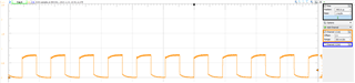
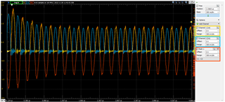
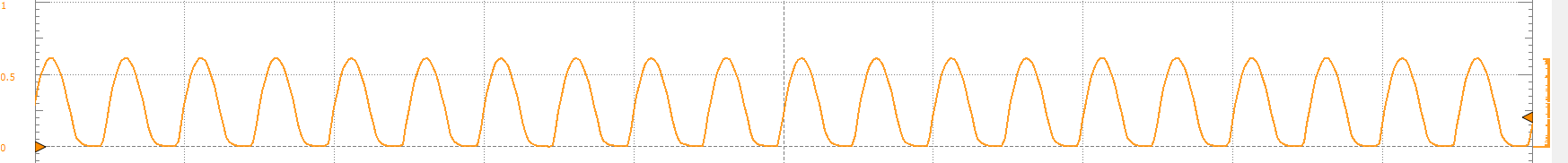
The signal should look similar to the shot below. Note that channel 1 has a probe on one side of the sensor and channel 2 is the other side of sensor. The math channel shows the combined signals.
Respected sir,
And We have a small dout regarding hardware in that based on our schematic IN0A and IN0B in both continuity is coming.In our FDC2112 From IN0A and IN0B continuity will come or not.
This is our code
/**
Generated Main Source File
Company:
Microchip Technology Inc.
File Name:
main.c
Summary:
This is the main file generated using PIC10 / PIC12 / PIC16 / PIC18 MCUs
Description:
This header file provides implementations for driver APIs for all modules selected in the GUI.
Generation Information :
Product Revision : PIC10 / PIC12 / PIC16 / PIC18 MCUs - 1.81.8
Device : PIC18F25K80
Driver Version : 2.00
*/
/*
(c) 2018 Microchip Technology Inc. and its subsidiaries.
Subject to your compliance with these terms, you may use Microchip software and any
derivatives exclusively with Microchip products. It is your responsibility to comply with third party
license terms applicable to your use of third party software (including open source software) that
may accompany Microchip software.
THIS SOFTWARE IS SUPPLIED BY MICROCHIP "AS IS". NO WARRANTIES, WHETHER
EXPRESS, IMPLIED OR STATUTORY, APPLY TO THIS SOFTWARE, INCLUDING ANY
IMPLIED WARRANTIES OF NON-INFRINGEMENT, MERCHANTABILITY, AND FITNESS
FOR A PARTICULAR PURPOSE.
IN NO EVENT WILL MICROCHIP BE LIABLE FOR ANY INDIRECT, SPECIAL, PUNITIVE,
INCIDENTAL OR CONSEQUENTIAL LOSS, DAMAGE, COST OR EXPENSE OF ANY KIND
WHATSOEVER RELATED TO THE SOFTWARE, HOWEVER CAUSED, EVEN IF MICROCHIP
HAS BEEN ADVISED OF THE POSSIBILITY OR THE DAMAGES ARE FORESEEABLE. TO
THE FULLEST EXTENT ALLOWED BY LAW, MICROCHIP'S TOTAL LIABILITY ON ALL
CLAIMS IN ANY WAY RELATED TO THIS SOFTWARE WILL NOT EXCEED THE AMOUNT
OF FEES, IF ANY, THAT YOU HAVE PAID DIRECTLY TO MICROCHIP FOR THIS
SOFTWARE.
*/
#include "mcc_generated_files/mcc.h"
#include <htc.h>
#include<pic18f25k80.h>
#include<stdio.h>
#include<string.h>
#include<stdlib.h>
#define RW RC1
#define RS RC0
#define ENA RC2
#define Chck_Engine PORTBbits.RB0
#define I2C_SLAVE 0x2A // Slave device I2C address
#define Ref_Value 500
unsigned char i2cReadData = 0;
unsigned char l_address = 0;
unsigned long result,Avg,Avg_A,R,x,result_2,Result_3,result_1,result_1_Flt1,result_1_Pre,Pre_Result_1,X_Count;
unsigned long Fuel_pos = 0;
unsigned long Fuel_pos1 = 0;
unsigned long Fuel_pos2 = 0;
unsigned long Fuel_pos3 = 0;
unsigned char read_byte = 0;
unsigned char read_byte1 = 0;
unsigned char read_byte2 = 0;
unsigned char read_byte3 = 0;
unsigned int i = 0;
unsigned int Result_LSB;
unsigned char Avg_A_Higher,Avg_A_Lower;
unsigned int Count,Timer_Load;
unsigned char check,check_1;
unsigned long Fuel_Data_1,Fuel_Data_2,Fuel_Data_3,Fuel_Data_4;
unsigned int Height;
// unsigned int Value;
unsigned long Value,Value_1;
unsigned int MSec;
// unsigned long Buffer[100];
//olatile const unsigned int Freq_Table1[];
// unsigned int result;
// char read_byte[2];
extern unsigned char i2cReadData;
unsigned int toggle_variable = 0;
unsigned char Counter_1;
unsigned int X1,X2,X3,Y1,Y3,Y2;
unsigned int Full_Tank,Empty_Tank,Var_Count_1,Var_Count_2;
unsigned int Counts_5;
// volatile const unsigned int Fuel_Count_Table[98]={5370,5541,5775,6054,6325,6699,6935,7188,7511,7796,8020,8345,8617,8917,9186,9509,9770,10096,10367,10665,10920,11238,11479,11743,12027,12294,12534,12807,13028,13332,13596,13865,14068,14411,14670,14940,15215,15510,15765,16052,16283,16597,16810,17069,17343,17646,17912,18210,18485,18877,19054,19409,19682,20060,20365,20685,20995,21347,21610,21878,22104,22415,22650,22893,23127,23475,23704,23890,24107,24390,24602,24915,25131,25410,25699,25930,26185,26428,26692,26931,27163,27415,27583,27878,28143,28429,28653,28901,29108,29357,29590,29785,30347,30558,30819,30847,30876};
// volatile const unsigned int Fuel_Count_Table[98]={5326,5535,5825,6119,6430,6745,6991,7278,7588,7880,8191,8429,8779,9064,9324,9609,9871,10153,10443,10754,10923,11200,11509,11781,12033,12301,12547,12821,13092,13391,13674,13900,14192,14461,14739,14984,15273,15532,15786,16037,16309,16562,16834,17081,17439,17709,17944,18198,18640,18780,19104,19275,19772,20174,20550,20863,21096,21349,21677,21970,22204,22538,22688,22963,23207,23431,23666,23953,24203,24469,24731,24933,25170,25440,25638,25913,26125,26416,26651,26917,27129,27430,27672,27936,28120,28354,28633,28895,29112,29385,29583,29855,30222,30225,30282,30309,30350};
volatile const unsigned int Fuel_Count_Table[98]={110,247,384,521,658,795,932,1069,1206,1343,1480,1617,1754,1891,2028,2165,2302,2439,2576,2713,2850,2987,3124,3261,3398,3535,3672,3809,3946,4083,4220,4357,4494,4631,4768,4905,5042,5179,5316,5453,5590,5727,5864,6001,6138,6275,6412,6549,6686,6823,6960,7097,7234,7371,7508,7645,7782,7919,8056,8193,8330,8467,8604,8741,8878,9015,9152,9289,9426,9563,9700,9837,9974,10111,10248,10385,10522,10659,10796,10933,11070,11207,11344,11481,11618,11755,11892,12029,12166,12303,12440,12577,12714,12851,12988,13125};
volatile const unsigned int Height_Table[98] ={0,5,10,15,20,25,30,35,40,45,50,55,60,65,70,75,80,85,90,95,100,105,110,115,120,125,130,135,140,145,150,155,160,165,170,175,180,185,190,195,200,205,210,215,220,225,230,235,240,245,250,255,260,265,270,275,280,285,290,295,300,305,310,315,320,325,330,335,340,345,350,355,360,365,370,375,380,385,390,395,400,405,410,415,420,425,430,435,440,445,450,455,460,465,470,475,480};
unsigned int LSB_1,MSB_1;
unsigned int LSB_2,MSB_2;
unsigned char Message1[16],Message2[16],X,SampleFlag,AvgFlag;
unsigned int Fuel_Level,CanFuelLevel,CAN_Recieve_Data,MiliSecond,Second,CANModuleEr,CANBusEr;
unsigned int i,z;
unsigned long Read_Data[10];//,AverageOut[25];
unsigned long LSB,MSB,MSB1,LSB1;
unsigned char OdometerCount,OdoMeterFlag;
unsigned char temp,Display,SampleAvg,Display1;
unsigned long V1,V2,V3,V4,V5,V6,V7,V8,V9,V10;
long double Fuel_Economy_3;
unsigned long long Fuel_Economy,Fuel_Economy_1,Fuel_data,AvgFuel;
unsigned long long FuelEconomyFlag;
unsigned long buffer_Pre[26];
unsigned char s_count_Pre;
unsigned long long total_value_Pre;
unsigned char cnt_Pre;
unsigned long long avg_val_Pre;
unsigned int buffer[301];
unsigned char s_count,Done_Flag;
unsigned long long total_value;
unsigned int cnt;
unsigned long long avg_val;
unsigned long buffer_Flt1[201];
unsigned char s_count_Flt1;
unsigned long long total_value_Flt1;
unsigned char cnt_Flt1;
unsigned long long avg_val_Flt1;
unsigned int Holder[200];
void Initialize(void);
void LCD_Init(void);
void LCDDelay(unsigned int Delay);
void LCD_Display(void);
void CAN_Init(void);
//void Nibble_Send(unsigned char Send_Data);
#define I2C_WRITE 0
#define I2C_READ 1
void I2C_Init(const unsigned long c) {
SSPCON1 = 0x28; // Set the I2C master mode and enable the serial port
SSPCON2 = 0x00; // Clear control register 2
// SSPADD = (_XTAL_FREQ / (4 * c)) - 1; // Set the I2C clock speed
SSPADD = (40000000 / (4 * 100000)) - 1;
SSPSTAT = 0x00; // Clear status register
}
void i2c_Start() {
SEN = 1; // Send the start bit
while (!SSPIF); // Wait for the start bit to be sent
SSPIF = 0; // Clear the interrupt flag
}
void i2c_Restart(void){
RSEN = 1; // Send a repeated start bit
while (!SSPIF); // Wait for the repeated start bit to be sent
SSPIF = 0; // Clear the interrupt flag
}
void i2c_Stop() {
PEN = 1; // Send the stop bit
while (!SSPIF); // Wait for the stop bit to be sent
SSPIF = 0; // Clear the interrupt flag
}
void i2c_Write(unsigned char data) {
SSPBUF = data; // Write data to the buffer
while (!SSPIF); // Wait for the data to be sent
SSPIF = 0; // Clear the interrupt flag
}
unsigned char i2c_Read(unsigned char ack) {
RCEN = 1; // Enable reception
while (!SSPIF); // Wait for the data to be received
SSPIF = 0; // Clear the interrupt flag
if (ack) {
ACKDT = 0; // Acknowledge the data
} else {
ACKDT = 1; // Not acknowledging the data
}
ACKEN = 1; // Enable the acknowledge sequence
return SSPBUF; // Return received data
}
void i2c_Wait(void){
while ( ( SSPCON2 & 0x1F ) || ( SSPSTAT & 0x04 ) );
}
void i2c_Address(unsigned char address, unsigned char mode)
{
l_address=address<<1;
l_address+=mode;
i2c_Wait();
SSPBUF = l_address;
}
//unsigned char ECAN_Receive(void);
void delay(unsigned int value)
{
while(value-- != 0);
}
void i2c_FDC_command(unsigned char address, unsigned char command , unsigned char command1)
{
i2c_Start(); // send Start
i2c_Address(I2C_SLAVE, I2C_WRITE); // Send slave address - write operation
i2c_Write(address); // DATA WRITE
// i2c_Address(I2C_SLAVE, I2C_WRITE); // Send slave address - write operation
i2c_Write(command); // DATA WRITE
// i2c_Address(I2C_SLAVE, I2C_WRITE); // Send slave address - write operation
i2c_Write(command1); // DATA WRITE
i2c_Stop(); // send Stop
}
void CalculateCount(void)
{
Counter_1 = 97;
while (Counter_1 > 0)
{
if(result_1 >= (Fuel_Count_Table[Counter_1-1]) && (result_1 <= (Fuel_Count_Table[Counter_1])))
{
break;
}
Counter_1--;
X1 = Fuel_Count_Table[Counter_1-1];
X2 = result_1;
X3 = Fuel_Count_Table[Counter_1];
Y1 = Height_Table[Counter_1-1];
Y3 = Height_Table[Counter_1];
}
}
//// Send a command to ic
//void i2c_FDC_command(unsigned char address, unsigned char command)
//{
// i2c_Start(); // send Start
// i2c_Address(I2C_SLAVE, I2C_WRITE); // Send slave address - write operation
// i2c_Write(address); // DATA WRITE
// i2c_Write(command); // DATA WRITE
// i2c_Stop(); // send Stop
//}
// Read a char from ic
//unsigned char i2c_FDC_read(unsigned char address)
void i2c_FDC_read(unsigned char address)
{
// Read one byte
i2c_Start(); // send Start
i2c_Address(I2C_SLAVE, I2C_WRITE); // Send slave address - write operation
i2c_Write(address); // DATA WRITE
i2c_Restart(); // Restart
i2c_Address(I2C_SLAVE, I2C_READ); // Send slave address - read operation
read_byte = i2c_Read(1); // Read one byte
read_byte1 = i2c_Read(0);
// read_byte2 = i2c_Read(1);
// read_byte3 = i2c_Read(0);
// If more than one byte to be read, (0) should
// be on last byte only
// e.g.3 bytes= i2c_Read(1); i2c_Read(1); i2c_Read(0);
i2c_Stop(); // send Stop
}
void i2c_FDC_read_2(unsigned char address)
{
// Read one byte
i2c_Start(); // send Start
i2c_Address(I2C_SLAVE, I2C_WRITE); // Send slave address - write operation
i2c_Write(address); // DATA WRITE
i2c_Restart(); // Restart
i2c_Address(I2C_SLAVE, I2C_READ); // Send slave address - read operation
// read_byte = i2c_Read(1); // Read one byte
// read_byte1 = i2c_Read(1);
read_byte2 = i2c_Read(1);
read_byte3 = i2c_Read(0);
// If more than one byte to be read, (0) should
// be on last byte only
// e.g.3 bytes= i2c_Read(1); i2c_Read(1); i2c_Read(0);
i2c_Stop(); // send Stop
}
void Initialize()
{
OSCCON=0b01111111;
OSCCON2=0b00001000;
OSCTUNE=0b01000000;
ANCON0=0x00; // Analog @portA disabled
ANCON1=0x00;
ADCON0=0x00;
CM1CON=0x00;
CM2CON=0x00;
INTCON2=0x04; // PORTB Pull up depends on TRIS of corresponding Bit, Timer0 High Priority Interrupt
INTCON3=0x00;
HLVDCON=0x00;
CIOCON=0x00;
TXSTA1=0x00;
RCSTA1=0x00;
TXSTA2=0x00;
RCSTA2=0x00;
ODCON=0x00; // OPen Drain Disabled
TMR0L=224; // 1 MS Interrupt
TMR0H=0;
INTCON=0xE0; // GIE,PEIE,TMR0 Enabled, INT,RBINT Disabled
T0CON=0xC6; // TMR0 8 BIT, Prescalar 1:128
/* PMD0=0xfE;
PMD1=0b11111110; // TMR0 Module Enabled
PMD2=0b00001011;
LATA=0;
PORTA = 0;
TRISA = 0X00;
LATB=0;
PORTB = 0;
TRISB = 0X0F;
TRISCbits.TRISC7 = 1;
TRISCbits.TRISC6 = 0;
TRISCbits.TRISC5 = 0;
TRISBbits.TRISB5 = 0;
WPUB = 0xFF;*/
}
/*void CAN_Receive(void)
{
CANCON=0b11101000; // Configuration Mode
while(CANCONbits.REQOP<4);
ECANCON=0x00; // Mode 0 ,Legacy Mode
RXB0CON=0b00000000; // Receive only valid messages with standard identifier
// RXB1CON=0x00; // All Disabled
RXERRCNT=0x00;
// RXF0SIDH=0b11000111; //0b11001010; // Distance
// RXF0SIDL=0b11101010; //0b11000000;
// RXF0EIDH=0b11000001; //0x00; ////18FE563Dh
// RXF0EIDL=0b00000000; //0b00011111;
RXF0SIDH=0b11000111; // Distance
RXF0SIDL=0b11101011;
RXF0EIDH=0b00110000; // 18FF3012 ID
RXF0EIDL=0b00010010;
// TXB0SIDH=0b11000111; //
// TXB0SIDL=0b11101011;
// TXB0EIDH=0b00110000; // 18FF3012 ID
// TXB0EIDL=0b00010010;
RXM0SIDH=0xFF; // Mask Bits
RXM0SIDL=0xFF;
RXM0EIDH=0xFF;
RXM0EIDL=0xFF;
RXF1SIDH=0b11000111; //
RXF1SIDL=0b11101011;
RXF1EIDH=0b00110000; // 18FF3012 ID
RXF1EIDL=0b00010010;
// RXF1SIDH=0b11000111; //0b11001010; fuel economy // Filter Bits
// RXF1SIDL=0b11101010; //0b11000000;
// RXF1EIDH=0b11110010; //0x00; ////18FE563Dh
// RXF1EIDL=0b00000000; //0b00011111;
RXM1SIDH=0xFF; // Mask Bits
RXM1SIDL=0xFF;
RXM1EIDH=0xFF;
RXM1EIDL=0xFF;
BRGCON1=0b00000011; // BAUD RATE 250Kb/s SJW=1TQ
BRGCON2=0b10010000; // PS1=3TQ , PTS=1TQ
BRGCON3=0b00000010;
CIOCON=0b01110001; // oscillator as the source of the CAN system clock
RXB0DLC=0b00001000;
CANCON=0x00; // Normal Mode
while(CANCONbits.REQOP!=0);
TXERRCNT=0x00;
RXERRCNT=0x00;
CANSTAT=0b01101100;
PIR5=0x00;
PIE5=0b10100001;
IPR5=0xff;
RXB0CON=0b00000000;
PIR5=0x00;
}*/
/*void Nibble_seperat()
{
for(i=0;i<=3;i++) //3
{
temp=Display%10;
Display=Display/10;
temp=temp+48;
if(i==1)
{
i=2;
}
Message2[6-i]=temp; //6
Message2[5]=46;
}
}*/
/*void CAN_Transmit(void)
{
//+++++++++++++++++++++++++++++++++++++++++++++++++++++Transmission +++++++++++++++++++++++
CANCON=0b11101000;
while(CANCONbits.REQOP<4);
ECANCON=0x00;
TXB0CON=0b00000011; // TXREQ to be set at transmition
BRGCON1=0b00000011; // BAUD RATE 250Kb/s SJW=1TQ 0x84 0x81
BRGCON2=0b10010000; // PS1=3TQ , PTS=1TQ 0xb8 0xb8
BRGCON3=0b00000010;
CIOCON=0b11100001;
CANCON=0b00001000;
while(CANCONbits.REQOP!=0);
TXERRCNT=0x00;
RXERRCNT=0x00;
PIR5=0x00;
PIE5=0b10100100;
IPR5=0xff;
TXB0CONbits.TXREQ = 0;
// TXB0SIDH=0b11000111; //
// TXB0SIDL=0b11101010;
// TXB0EIDH=0b11110010; // 18FEF200 ID
// TXB0EIDL=0b00000000;
TXB0SIDH=0b11000111; //
TXB0SIDL=0b11101011;
TXB0EIDH=0b00110000; // 18FF3012 ID
TXB0EIDL=0b00010010;
//TXB0DLCbits.DLC = 1;
TXB0DLC = 0b00001000;
TXB0D4=1;
TXB0D5=0;
TXB0D6=1;
TXB0D7=0;
TXB0CONbits.TXREQ = 1;
PIR5=0x00;
}*/
void LCD_Display()
{
unsigned char LCD_Count;
// LCD Line 1
for(LCD_Count=0; LCD_Count<16; LCD_Count++)
{
EUSART2_Write(Message1[LCD_Count]);
}
for(LCD_Count=0; LCD_Count<16; LCD_Count++)
{
EUSART2_Write(Message2[LCD_Count]);
}
}
void UART1_uitoa(unsigned int number, char* ascii_number)
{
unsigned int position=0;
unsigned int length=0 ;
unsigned int temp_int=number;
if (number==0)
{
*( ascii_number)='0';
*( ascii_number+1)='\0';
}
else
{
while (temp_int)
{
temp_int/=10;
length++;
}
for (position=length;position>0;position--)
{
*( ascii_number + position-1) = '0' + number % 10;
number /= 10;
}
*( ascii_number + length) = '\0';
}
}
void SendStringSerially(const unsigned char* st)
{
while(*st)
EUSART2_Write(*st++);
}
void UART1_put_int(unsigned int number)
{
char ascii_number[ 11 ];
UART1_uitoa( number, ascii_number ) ;
SendStringSerially( ascii_number ) ;
}
int main()
{
unsigned int i;
//CANModuleEr=0;
//CANBusEr=0;
TRISC3 = 1; // SDA pin as input
TRISC4 = 1; // SCL pin as input
I2C_Init(100000);
SYSTEM_Initialize();
//CAN_Receive();
//CAN_Transmit();
// i2c_Init(); // Start I2C as Master 100KHz
strcpy(Message1," I2c initialized ");
delay(1000);
i2c_FDC_command(0x1A,0x28,0x01); //single channel configure
i2c_FDC_command(0x08,0x83,0x29); //CONVERSION TIME 6.66ms(100SPS)
i2c_FDC_command(0x09,0x83,0x29); //CONVERSION TIME 6.66ms(100SPS)
i2c_FDC_command(0x0A,0x83,0x29); //CONVERSION TIME 6.66ms(100SPS)
i2c_FDC_command(0x10,0x00,0x0A); //Settling time for channel zero
i2c_FDC_command(0x11,0x00,0x0A); //Settling time for channel zero
i2c_FDC_command(0x12,0x00,0x0A); //Settling time for channel zero
i2c_FDC_command(0x14,0x20,0x02); //To set drive for channel 0
i2c_FDC_command(0x15,0x20,0x02); //To set drive for channel 0
i2c_FDC_command(0x16,0x20,0x02); //To set drive for channel 0
i2c_FDC_command(0x19,0x00,0x00); //CONVERSION TIME 6.66ms(100SPS)
i2c_FDC_command(0x1B,0xC2,0x0D); //C20D //MUX_CONFIG
// i2c_FDC_command(0x1E,0x7C,0x00); //Sensor drive current
i2c_FDC_command(0x1E,0x7C,0x00); //Sensor drive current
i2c_FDC_command(0x1F,0x7C,0x00); //Sensor drive current
i2c_FDC_command(0x20,0x7C,0x00); //Sensor drive current
// i2c_FDC_command(0x1A,0x16,0x01); //CONFIG WITH SLEEP Disable external OSC
i2c_FDC_command(0x1A,0x16,0x01); //CONFIG WITH SLEEP Disable Internal OSC
// i2c_FDC_command(0x14,0x20,0x01); //To set drive for channel 0
strcpy(Message1," I2c Configuration ");
/*//LCD_Init();
strcpy(Message1," M.T.B.L. ");
strcpy(Message2," R.D.E.P.L ");
LCD_Display();
for(i=0;i<65500;i++);
for(i=0;i<65500;i++);
for(i=0;i<65500;i++);
for(i=0;i<65500;i++);
for(i=0;i<65500;i++);
for(i=0;i<65500;i++);
Fuel_Economy=0;
z=0;
X=20;
SampleFlag=0;
AvgFlag=1;
FuelEconomyFlag=1;*/
RC5 = 0;
RB5 = 0;
Done_Flag = 1;
while(1)
{
SendStringSerially("hello\n \r");
i2c_FDC_read(0x00);
SendStringSerially(" I2c data Read Byte 0:");//READ SINGLE FROM MSB
Fuel_pos = read_byte;//*1.27; MSB
UART1_put_int(Fuel_pos);
SendStringSerially("\t");
Fuel_pos1 = read_byte1;//*1.27;LSB
UART1_put_int(Fuel_pos1);
SendStringSerially("\n\r");
NOP();
i2c_FDC_read_2(0x01);
SendStringSerially(" I2c data Read Byte 1:");//READ SINGLE FROM MSB//READ SINGLE FROM LSB
Fuel_pos2 = read_byte2;//*1.27; MSB
UART1_put_int(Fuel_pos2);
SendStringSerially("\t");
Fuel_pos3 = read_byte3;//*1.27; LSB
UART1_put_int(Fuel_pos3);
SendStringSerially("\n\r");
Fuel_Data_4 = Fuel_pos3;
Fuel_Data_3 = Fuel_pos2;
Fuel_Data_2 = Fuel_pos1;
Fuel_Data_1 = Fuel_pos;
result = ((Fuel_Data_1<<24)|(Fuel_Data_2<<16)|(Fuel_Data_3<<8)|Fuel_Data_4);
MSec = 0;
SendStringSerially(" Result:");
UART1_put_int(result);
SendStringSerially("\n\r");
// while(MSec<36);
// LCDDelay(7550);
// LCDDelay(60000);
// LCDDelay(60000);
// LCDDelay(60000);
// LCDDelay(60000);
// LCDDelay(60000);
// Value_1 = (result)/1000;
Value = (result)/1000;
//300 counts running Avrage
buffer[0]=Value;
for(cnt=0;cnt<300;cnt++) //75s_count>=60
{
buffer[cnt+1] = buffer[cnt] ;
}
for(cnt=0;cnt<300;cnt++) //75s_count>=60
{
total_value += buffer[cnt];
}
avg_val_Flt1 = total_value/300; //75s_count>=60
result_1 = avg_val_Flt1; // Final Result
total_value = 0;
if(result_1 > 26544) // To control the max count coming form sensor
{ SendStringSerially(" Result Max:");
UART1_put_int(result_1);
SendStringSerially("\n\r");
//result_1 = 26544;
}
else if(result_1 < 24792) // To control the min count coming form sensor
{
SendStringSerially(" Result Min:");
UART1_put_int(result_1);
SendStringSerially("\n\r");
// result_1 = 24792;
}
Height = ((26544 - result_1)*50)/219; //138
Counts_5 = 26544 - result_1;
AvgFuel=Fuel_Economy_1/FuelEconomyFlag;
Display1 = AvgFuel;
SendStringSerially(" Avg Fuel:");
UART1_put_int(Display1);
SendStringSerially("\n\r");
if(CANModuleEr==0 && CANBusEr==0)
{
strcpy(Message1," Fuel Economy ");
strcpy(Message2," km/L ");
if(OdoMeterFlag==1)
{
AvgFuel=Fuel_Economy_1/FuelEconomyFlag;
Display1 = AvgFuel;
SendStringSerially(" Avg Fuel:");
UART1_put_int(Display1);
SendStringSerially("\n\r");
OdoMeterFlag=0;
FuelEconomyFlag=1;
Fuel_Economy_1=0;
// Display=Display1;
// Nibble_seperat();
}
//Display1=Fuel_Economy_3;
Display=Display1;
//Nibble_seperat();
}
/*else
{
if(CANBusEr==1)
{
strcpy(Message1," ERROR ");
strcpy(Message2," CAN BUS ");
}
else
{
strcpy(Message1," ERROR ");
strcpy(Message2," CAN MODULE ");
}
}
//LCD_Display();
}
}*/
/*void interrupt_isr(void)
{
if(TMR0IF==1)
{
MiliSecond++;
MSec++;
if(MiliSecond>=2000)
{
//---------------------Transmission---------------------------------------------//
// if(result<26485000)
// result = ((Fuel_Data_1<<24)|(Fuel_Data_2<<16)|(Fuel_Data_3<<8)|Fuel_Data_4);
//Height = (29008320-result)/4865; //4543; 26485000 //28260578 //2775551326341064
//Height = (result_1-5370)/54;
// CalculateCount();
// if(result_1>=110 && result_1<=13125)
// {
// Height = (((X2-X1)*(Y3-Y1))/(X3-X1))+Y1;
// LSB = (Height & 0xFF);
// MSB = ((Height & 0xFF00)>>8);
// }
//
// if(result_1<110)
// {
// Height = 0;
// }
// if(result_1>13125)
// {
// Height = 480;
// }
LSB = (Height & 0xFF);
MSB = ((Height & 0xFF00)>>8);
// Value =(29199999-result)/100; //29755739
LSB_1 = (result_1 & 0xFF);
MSB_1 = ((result_1 & 0xFF00)>>8);
LSB_2 = (Counts_5 & 0xFF);
MSB_2 = ((Counts_5 & 0xFF00)>>8);
// result_1 = ((MSB_1<<8)|LSB_1);
Second++;
TXB0CONbits.TXREQ = 0;
TXB0SIDH=0b11000111; //
TXB0SIDL=0b11101011;
TXB0EIDH=0b00110000; // 18FF3012 ID
TXB0EIDL=0b00010010;
// TXB0D0= Fuel_pos; //IBM Big Endian
// TXB0D1= Fuel_pos1;
// TXB0D2= Fuel_pos2;
// TXB0D3= Fuel_pos3;
// TXB0D0= Fuel_pos3; //Intel Little Endian
// TXB0D1= Fuel_pos2;
// TXB0D2= Fuel_pos1;
// TXB0D3= Fuel_pos;
TXB0D0= LSB_1; //result_1 LSB; //Intel Little Endian
TXB0D1= MSB_1; //result_1 MSB;
TXB0D2= LSB_2; //Counts_5 LSB
TXB0D3= MSB_2; //Counts_5 MSB
TXB0D4= LSB; //Height LSB
TXB0D5= MSB; //Height MSB
TXB0D6= 00;
TXB0D7= 00;
TXB0CONbits.TXREQ = 1;
MiliSecond = 0;
//---------------------Transmission---------------------------------------------//
//---------------------Rx---------------------------------------------//
// result = ((Read_Data[0]<<24)|(Read_Data[1]<<16)|(Read_Data[2]<<8)|Read_Data[3]);
// Height = Read_Data[5]<<8|Read_Data[4];
// MiliSecond = 0;
//---------------------Rx---------------------------------------------//
}
TMR0IF=0;
TMR0IE=1;
TMR0L=224;
TMR0H=0;
}
if(RXB0IF==1)
{
CANModuleEr=0;
CANBusEr=0;
Read_Data[0] = RXB0D0; //Byte1 Byte1 Fuel Rate LSB
Read_Data[1] = RXB0D1; //Byte2 Byte1 Fuel Rate MSB
Read_Data[2] = RXB0D2; //Byte1 Instantaneoue Fuel Economy LSB} WANTED
Read_Data[3] = RXB0D3; //Byte1 Instantaneoue Fuel Economy MSB} WANTED
Read_Data[4] = RXB0D4; //Byte1
Read_Data[5] = RXB0D5; //Byte1
Read_Data[6] = RXB0D6; //Byte1
Read_Data[7] = RXB0D7; //Byte1
//MSB = (Read_Data[3] << 8);
//LSB = (Read_Data[2] & 0x00FF);
//Fuel_Economy = (MSB|LSB);
RXB0CONbits.RXFUL=0;
RXB0IF=0;
PIE5bits.RXB0IE=1;
}
if(ERRIF==1)
{
CANModuleEr=1;
RXERRCNT=0x00;
TXERRCNT=0x00;
ERRIF=0;
}
if(TXB0IF==1)
{
CANModuleEr=0;
CANBusEr=0;
// Read_Data[0]=TXB0D0; //Byte1 Fuel Rate LSB
// Read_Data[1]=TXB0D1; //Byte2 Fuel RAte MSB
// Read_Data[2]=TXB0D2; //Byte3 Instantaneoue Fuel Economy LSB} WANTED
// Read_Data[3]=TXB0D3; //Byte4 Instantaneoue Fuel Economy MSB}
Read_Data[4]=TXB0D4; //Byte5
Read_Data[5]=TXB0D5; //Byte6
Read_Data[6]=TXB0D6; //Byte7
Read_Data[7]=TXB0D7; //Byte8
// MSB=(Read_Data[3]<<8); //1111101000000000
// LSB = (Read_Data[2] & 0x00FF); //11111010 194
// Fuel_Economy = MSB|LSB;
TXB0IF=0;
}
if(IRXIF==1)
{
CANBusEr=1;
IRXIF=0;
}*/
}
}
FDC2112 code we modified
I am not sure I understand your doubt. Can you please clarify?
The I2C communication needs to be working before you will see any output.
Respected sir,
our FDC2112 IC sensor is not working we are trying on it .Previous mentioned code is for pic and FDC2112 code.We are asking that can you send FDC2112 code
Based on previuosly sent code we modified the code but Sensor is not sensing.Can you share what was problem whether hardware issue or software issue.
/**
Generated Main Source File
Company:
Microchip Technology Inc.
File Name:
main.c
Summary:
This is the main file generated using PIC10 / PIC12 / PIC16 / PIC18 MCUs
Description:
This header file provides implementations for driver APIs for all modules selected in the GUI.
Generation Information :
Product Revision : PIC10 / PIC12 / PIC16 / PIC18 MCUs - 1.81.8
Device : PIC16F1823
Driver Version : 2.00
*/
/*
(c) 2018 Microchip Technology Inc. and its subsidiaries.
Subject to your compliance with these terms, you may use Microchip software and any
derivatives exclusively with Microchip products. It is your responsibility to comply with third party
license terms applicable to your use of third party software (including open source software) that
may accompany Microchip software.
THIS SOFTWARE IS SUPPLIED BY MICROCHIP "AS IS". NO WARRANTIES, WHETHER
EXPRESS, IMPLIED OR STATUTORY, APPLY TO THIS SOFTWARE, INCLUDING ANY
IMPLIED WARRANTIES OF NON-INFRINGEMENT, MERCHANTABILITY, AND FITNESS
FOR A PARTICULAR PURPOSE.
IN NO EVENT WILL MICROCHIP BE LIABLE FOR ANY INDIRECT, SPECIAL, PUNITIVE,
INCIDENTAL OR CONSEQUENTIAL LOSS, DAMAGE, COST OR EXPENSE OF ANY KIND
WHATSOEVER RELATED TO THE SOFTWARE, HOWEVER CAUSED, EVEN IF MICROCHIP
HAS BEEN ADVISED OF THE POSSIBILITY OR THE DAMAGES ARE FORESEEABLE. TO
THE FULLEST EXTENT ALLOWED BY LAW, MICROCHIP'S TOTAL LIABILITY ON ALL
CLAIMS IN ANY WAY RELATED TO THIS SOFTWARE WILL NOT EXCEED THE AMOUNT
OF FEES, IF ANY, THAT YOU HAVE PAID DIRECTLY TO MICROCHIP FOR THIS
SOFTWARE.
*/
//#include "mcc_generated_files/mcc.h"
/*
Main application
*/
#include <pic.h>
#include <math.h>
#include <htc.h>
#include "i2c.h"
__CONFIG (FOSC_INTOSC & WDTE_OFF & PWRTE_ON & MCLRE_OFF & CP_ON & CLKOUTEN_OFF & BOREN_ON & FCMEN_OFF & STVREN_ON & PLLEN_OFF & BORV_25 & LVP_OFF);
#define _XTAL_FREQ 16000000
#define I2C_SLAVE 0x2A
// unsigned char i;
unsigned long result,Avg,Avg_A,R,x,result_2,Result_3;
unsigned long Fuel_pos = 0;
unsigned long Fuel_pos1 = 0;
unsigned long Fuel_pos2 = 0;
unsigned long Fuel_pos3 = 0;
unsigned char read_byte = 0;
unsigned char read_byte1 = 0;
unsigned char read_byte2 = 0;
unsigned char read_byte3 = 0;
unsigned int i = 0;
unsigned int Result_LSB;
unsigned char Avg_A_Higher,Avg_A_Lower;
unsigned int Count,Timer_Load;
unsigned char check,check_1;
// unsigned long Buffer[100];
//olatile const unsigned int Freq_Table1[];
// unsigned int result;
// char read_byte[2];
extern unsigned char i2cReadData;
unsigned int toggle_variable = 0;
unsigned char i2c_Read(unsigned char ack);
extern void i2c_Address(unsigned char address, unsigned char mode);
extern void i2c_Write(unsigned char data);
extern void i2c_Stop(void);
extern void i2c_Restart(void);
extern void i2c_Start(void);
extern void i2c_Wait(void);
extern void i2c_Init(void);
void init_pwm()
{
T1CONbits.TMR1ON = 1;
T1GCONbits.TMR1GE = 0;
//Osc.Circuit On T1OSI/T1OSO Pins
// T1CONbits.TMR1CS1 = 1;
// T1CONbits.TMR1CS0 = 0;
T1CONbits.TMR1CS1 = 0;
T1CONbits.TMR1CS0 = 1;
// T1CONbits.T1OSCEN = 1;
T1CONbits.T1OSCEN = 0;
// wait_ms(50); //start-up and stabilization time
//select Prescaler 1:8
// T1CONbits.T1CKPS1=1;
// T1CONbits.T1CKPS0=1;
T1CONbits.T1CKPS1=0;
T1CONbits.T1CKPS0=0;
//Asynchronous Counter
// T1CONbits.NOT_T1SYNC = 1;
//TNR1H, TMR1L and TMR1IF should be cleared before enabling the interrupt
TMR1H = 0x00;
TMR1L = 0x00;
PIR1bits.TMR1IF = 0;
//enable overflow interrupt (0xFFFF -> 0x0000)
PIE1bits.TMR1IE = 1;
INTCONbits.PEIE = 1;
INTCONbits.GIE = 1;
//oszillator circuit : f=32,768 kHz
//instruction periode = 1/f = 30,52 us = T
//prescaller value = 1:8
//timer0 rate = 8 * T = 8 * 30,52 us = 244,16 us (1 pulse)
//16-bit-timer
//interrupt intervall = 10 s
//pulses to interrupt = 10 s / 244,16 us = 40956,7 = 40957
//decimal: counter start = 65535-40957 = 24578 -> 0x6002
//Interrupt after 10s
/*TMR1H = 0x60; //high byte
TMR1L = 0x02; //low byte*/
// 1s
// TMR1H = 0xEF; //high byte
// TMR1L = 0xFF; //low byte
}
void interrupt
timer1_isr(void)
{
if(PIR1bits.TMR1IF == 1) //interrupt from Timer1?
{
TMR1H = Avg_A_Higher;
TMR1L = Avg_A_Lower;
PIR1bits.TMR1IF = 0;
PORTAbits.RA5 = ~PORTAbits.RA5; //removed
}
}
// Send a command to ic
void i2c_FDC_command(unsigned char address, unsigned char command , unsigned char command1)
{
i2c_Start(); // send Start
i2c_Address(I2C_SLAVE, I2C_WRITE); // Send slave address - write operation
i2c_Write(address); // DATA WRITE
// i2c_Address(I2C_SLAVE, I2C_WRITE); // Send slave address - write operation
i2c_Write(command); // DATA WRITE
// i2c_Address(I2C_SLAVE, I2C_WRITE); // Send slave address - write operation
i2c_Write(command1); // DATA WRITE
i2c_Stop(); // send Stop
}
//// Send a command to ic
//void i2c_FDC_command(unsigned char address, unsigned char command)
//{
// i2c_Start(); // send Start
// i2c_Address(I2C_SLAVE, I2C_WRITE); // Send slave address - write operation
// i2c_Write(address); // DATA WRITE
// i2c_Write(command); // DATA WRITE
// i2c_Stop(); // send Stop
//}
// Read a char from ic
//unsigned char i2c_FDC_read(unsigned char address)
void i2c_FDC_read(unsigned char address)
{
// Read one byte
i2c_Start(); // send Start
i2c_Address(I2C_SLAVE, I2C_WRITE); // Send slave address - write operation
i2c_Write(address); // DATA WRITE
i2c_Restart(); // Restart
i2c_Address(I2C_SLAVE, I2C_READ); // Send slave address - read operation
read_byte = i2c_Read(1); // Read one byte
read_byte1 = i2c_Read(0);
// read_byte2 = i2c_Read(1);
// read_byte3 = i2c_Read(0);
// If more than one byte to be read, (0) should
// be on last byte only
// e.g.3 bytes= i2c_Read(1); i2c_Read(1); i2c_Read(0);
i2c_Stop(); // send Stop
}
void i2c_FDC_read_2(unsigned char address)
{
// Read one byte
i2c_Start(); // send Start
i2c_Address(I2C_SLAVE, I2C_WRITE); // Send slave address - write operation
i2c_Write(address); // DATA WRITE
i2c_Restart(); // Restart
i2c_Address(I2C_SLAVE, I2C_READ); // Send slave address - read operation
// read_byte = i2c_Read(1); // Read one byte
// read_byte1 = i2c_Read(1);
read_byte2 = i2c_Read(1);
read_byte3 = i2c_Read(0);
// If more than one byte to be read, (0) should
// be on last byte only
// e.g.3 bytes= i2c_Read(1); i2c_Read(1); i2c_Read(0);
i2c_Stop(); // send Stop
}
void delay(unsigned int value)
{
while(value-- != 0);
}
void Initialize_system()
{
OSCCON = 0b01111010; // set internal osc to 16MHz
ANSELA = 0;
ANSELC = 0;
TRISAbits.TRISA4 = 0; //ADRESS SELECTION PIN
PORTAbits.RA4 = 0; //ADRESS SELECTION PIN
TRISCbits.TRISC2=0; //shutdown Pin Low
PORTCbits.RC2=0; //shutdown Pin Low
TRISAbits.TRISA5 = 0; //PWM OUTPUT
PORTAbits.RA5 = 0; //PWM OUTPUT PIN
IOCAP = 0;
IOCAN = 0;
ADCON0bits.ADON = 0;
DACCON0bits.DACEN = 0;
CM1CON0bits.C1ON = 0;
CM2CON0bits.C2ON = 0;
}
void uart_init(void)
{
// Set the EUSART module to the options selected in the user interface.
// ABDOVF no_overflow; SCKP Non-Inverted; BRG16 16bit_generator; WUE disabled; ABDEN disabled;
BAUDCON = 0x08;
// SPEN enabled; RX9 8-bit; CREN enabled; ADDEN disabled; SREN disabled;
RCSTA = 0x90;
// TX9 8-bit; TX9D 0; SENDB sync_break_complete; TXEN enabled; SYNC asynchronous; BRGH hi_speed; CSRC slave;
TXSTA = 0x24;
// SPBRGL 12;
SPBRGL = 0x0C;
// SPBRGH 0;
SPBRGH = 0x00;
// eusartRxLastError.status = 0;
}
void uart_Write(unsigned char txData)
{
while(0 == PIR1bits.TXIF)
{
}
TXREG = txData; // Write the data byte to the USART.
}
void UART1_uitoa(unsigned int number, char* ascii_number)
{
unsigned int position=0;
unsigned int length=0 ;
unsigned int temp_int=number;
if (number==0)
{
*( ascii_number)='0';
*( ascii_number+1)='\0';
}
else
{
while (temp_int)
{
temp_int/=10;
length++;
}
for (position=length;position>0;position--)
{
*( ascii_number + position-1) = '0' + number % 10;
number /= 10;
}
*( ascii_number + length) = '\0';
}
}
void SendStringSerially( unsigned char* st)
{
while(*st)
uart_Write(*st++);
}
void UART1_put_int(unsigned int number)
{
char ascii_number[ 11 ];
UART1_uitoa( number, ascii_number ) ;
SendStringSerially( ascii_number ) ;
}
void main(void)
{
PORTAbits.RA4 = 0;
Initialize_system();
init_pwm();
// i2c_Init();
OSCCON = 0x3A;
// TUN 0;
OSCTUNE = 0x00;
// SBOREN disabled;
BORCON = 0x00;
WDTCON = 0x16;
LATA = 0x00;
LATC = 0x00;
/**
TRISx registers
*/
TRISA = 0x3F;
TRISC = 0x3F;
/**
ANSELx registers
*/
ANSELC = 0x0F;
ANSELA = 0x17;
/**
WPUx registers
*/
WPUA = 0x00;
WPUC = 0x00;
OPTION_REGbits.nWPUEN = 1;
/**
APFCONx registers
*/
APFCON = 0x00;
uart_init();
i2c_Init(); // Start I2C as Master 100KHz
delay(1000);
i2c_FDC_command(0x1A,0x00,0x00); //single channel configure
i2c_FDC_command(0x08,0x83,0x29); //RCount
i2c_FDC_command(0x19,0x00,0x00); //error_configure
i2c_FDC_command(0x10,0x00,0x0A); //SETTLE_COUNT
i2c_FDC_command(0x14,0x20,0x02); //CLOCK_DIVIDERS
i2c_FDC_command(0x1E,0x7C,0x00); //DRIVE_CUTRRENT
i2c_FDC_command(0x1B,0xC2,0x0D); //MUX_CONGIG
i2c_FDC_command(0x1A,0x16,0x01);
/* i2c_FDC_command(0x08,0x83,0x29); //CONVERSION TIME 6.66ms(100SPS)
i2c_FDC_command(0x09,0x83,0x29); //CONVERSION TIME 6.66ms(100SPS)
i2c_FDC_command(0x0A,0x83,0x29); //CONVERSION TIME 6.66ms(100SPS)
i2c_FDC_command(0x10,0x00,0x0A); //Settling time for channel zero
i2c_FDC_command(0x11,0x00,0x0A); //Settling time for channel zero
i2c_FDC_command(0x12,0x00,0x0A); //Settling time for channel zero
i2c_FDC_command(0x14,0x20,0x02); //To set drive for channel 0
i2c_FDC_command(0x15,0x20,0x02); //To set drive for channel 0
i2c_FDC_command(0x16,0x20,0x02); //To set drive for channel 0
i2c_FDC_command(0x19,0x00,0x00); //CONVERSION TIME 6.66ms(100SPS)
i2c_FDC_command(0x1B,0xC2,0x0D); //C20D //MUX_CONFIG
// i2c_FDC_command(0x1E,0x7C,0x00); //Sensor drive current
i2c_FDC_command(0x1E,0x7C,0x00); //Sensor drive current
i2c_FDC_command(0x1F,0x7C,0x00); //Sensor drive current
i2c_FDC_command(0x20,0x7C,0x00); //Sensor drive current
// i2c_FDC_command(0x1A,0x16,0x01); //CONFIG WITH SLEEP Disable external OSC
i2c_FDC_command(0x1A,0x14,0x01); //CONFIG WITH SLEEP Disable Internal OSC
// i2c_FDC_command(0x14,0x20,0x01); //To set drive for channel 0*/
while (1)
{
PORTAbits.RA4 = 0;
// i2c_FDC_command(0x1A, 0x00); //single channel configure
// i2c_FDC_command(0x1A,0x16,0x01); //CONFIG WITH SLEEP Disabl
// i2c_FDC_read(0x01); //READ SINGLE CHANNEL DATA
if(Fuel_pos2<=Fuel_pos3)
{
}
if(result>=Fuel_pos3)
{
}
if(Avg_A_Lower>=Avg_A_Higher)
{
}
if(result_2>result)
{
}
if(Result_3>result)
{
}
SendStringSerially("hello\n \r");
i2c_FDC_read(0x00); //READ SINGLE FROM MSB
SendStringSerially(" I2c data Read Byte 0:");
Fuel_pos = read_byte;//*1.27;
UART1_put_int(Fuel_pos);
SendStringSerially("\t");
Fuel_pos1 = read_byte1;//*1.27;
UART1_put_int(Fuel_pos1);
SendStringSerially("\n\r");
NOP();
i2c_FDC_read_2(0x01); //READ SINGLE FROM LSB
SendStringSerially(" I2c data Read Byte 1:");
Fuel_pos2 = read_byte2;//*1.27;
UART1_put_int(Fuel_pos2);
SendStringSerially("\t");
Fuel_pos3 = read_byte3;//*1.27;
UART1_put_int(Fuel_pos3);
SendStringSerially("\n\r");
// i2c_FDC_read(0x18);
// check = read_byte;//*1.27;
// check_1 = read_byte1;//*1.27;
result = ((Fuel_pos<<24)|(Fuel_pos1<<16)|(Fuel_pos2<<8)|Fuel_pos3);
SendStringSerially(" Result:");
UART1_put_int(result);
SendStringSerially("\n\r");
// result = ((Fuel_pos1<<8)|(Fuel_pos));
// result_2 = ((Fuel_pos3<<8)|(Fuel_pos2));
// Result_3 = ((result_2<<8)|(result));
NOP();
// result = 25829888;//25829888;//28227067; 27028478
if(check == 0)
{
result = 25829888;
check = 1;
}
Count = 0;
x=0;
for(R=29000000;R>=x;R=R-8333) //8333 4994
{
Count++;
if(result>=R)
{
SendStringSerially(" Result Max:");
UART1_put_int(result);
x=result;
}
}
NOP();
x=0;
Timer_Load = 0;
for(R=480;R>=x;R--)
{
Timer_Load =Timer_Load+134;
if(Count>=R)
{
SendStringSerially(" count Min:");
UART1_put_int(result);
SendStringSerially("\n\r");
x=Count;
SendStringSerially(" Count:");
UART1_put_int(x);
SendStringSerially("\n\r");
}
}
NOP();
// Timer_Load = Timer_Load/10; // to increase the resolution Value /10
Avg_A_Lower = Timer_Load & 0x000000ff ;
SendStringSerially(" Timer_Load:");
UART1_put_int( Avg_A_Lower);
SendStringSerially("\n\r");
Avg_A_Higher =(Timer_Load & 0x0000ff00)>>8;
SendStringSerially(" Timer_Load:");
UART1_put_int( Avg_A_Higher);
SendStringSerially("\n\r");
delay(1000);
delay(1000);
delay(1000);
delay(1000);
delay(1000);
delay(1000);
delay(1000);
delay(1000);
delay(1000);
delay(1000);
delay(1000);
delay(1000);
delay(1000);
NOP();
}
}
/*uart_Write('H'); uart_Write('E'); uart_Write('l');
// Add your application code
}
}*/
/**
End of File
*/
Can you provide logic analyzer captures of the I2C traffic? From the last capture you shared, it did not look like you were generating a clock from the MCU.
We do not have PIC code available as this is a competitor to TI MCUs. There is some MSP430 reference code that you would reference below.
Respected sir,
previously send code we Already modified and converted to my code and check but nothing result and sensor is not sensing
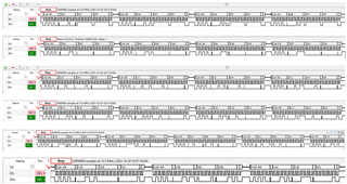
I checked on the FDC2114EVM. Please see the logic analyzer captures below of the I2C communication after power up. This writes the registers from 0x08 to 0x1A. You will see in the write of 0x1A, the device is set to active. After this, the MCU is reading 0x00 for the channel 0 conversion result. Are you able to take a similar logic analyzer capture of your system to compare?
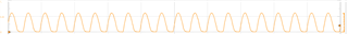
The resulting signal on the sensor should look something like the capture below where the frequency varies when the sensor capacitance is altered. This measurement was taken on 1 channel at the sensor and referenced to ground. You don't actually need to do a differential measurement for the capacitive sensor.
Respected sir,
From SCL and SDA we got similar pulse
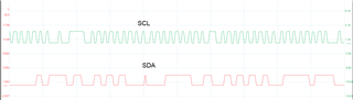
but from channel 0[IN0A and IN0B] we didnot received any pulse
Whether from Channel 0 [IN0A and IN0B] any pulse will generate or not?
Thanks for the shots. I looked over the schematic again to be sure something wasn't missed. I do see a problem with the VDD and GND pins of the device. From the schematic, it looks like 3.3V is applied to the GND pin and GND connected to the VDD pin. I would not expect I2C to work in this condition. Can you confirm on your board if this is indeed connected backwards?
Respected sir,
In our board we checked in FDC2112 VDD pin connected to VCC and GND pin Connected to GND. And I have a dout that in IN0A and IN0B pins any pulse will generate or not ? Can you share that waveform
The wave form at the sensor can be seen below. Can you share the details of your sensor? What is the capacitance? I want to be sure you are within the resonant frequency range.
Respected sir,
Detailes of sensor FDC2112 IC
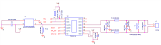
this was the schematic for FDC2112 IC
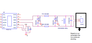
In our board this two ends are shorting.Whether this both ends short are not?
No, this should not be a direct short. I measure around 2.5ohms on the EVM. Can you provide the details of your capacitive sensing electrode design? Size, shape, and a image would be useful.
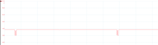
Even if you have no sensing electrode connected to J1, you should still see a signal. The scope capture below is from the EVM with the electrode disconnected.