Because of the holidays, TI E2E™ design support forum responses will be delayed from Dec. 25 through Jan. 2. Thank you for your patience.

This thread has been locked.

If you have a related question, please click the "Ask a related question" button in the top right corner. The newly created question will be automatically linked to this question.

PGA305: DAC codes for 4-20mA over I2C interface

Part Number: PGA305
Other Parts Discussed in Thread: USB2ANY

I'm using the PGA305 in an application where all the offset/gain compensation will be happening on a microcontroller and the PGA305 is being used as a resistive bridge interface and current output DAC driven over I2C.

From the 1.25V reference and 40kOhm resistance, I expected the 4mA DAC code to be 0x082f and the 20mA code to be 0x28eb corresponding to roughly 2uA / LSB.
However, on editing the contents of the DAC_REG0 resistors, I see that 4mA and 20mA points are roughly 0xc8 and 0x3e8 respectively, and the current output is not stable at any register value, drifting tens of uA.

I am using the following configuration to set it up

  1. Set 0b11 in the COMPENSATION_CONTROL register to disable the compensation engine and let the digital interface control the PGA resources.
  2. Set 0b1 in the DAC_CTRL_STATUS register to enable the DAC output.
  3. Set 0b0 in the DAC_CONFIG register to set the DAC in absolute reference mode.
  4. Set 0b1000 in the OP_STAGE_CTRL register to enable 4-20mA and disable the DAC voltage gain.

After that, for any 16bit unsigned DAC code, I write the LSB to the DAC_REG0_1 register and the (MSB & 0x3f) to the DAC_REG0_2 register.

I am using the PGA305 current output with the connections according to the following schematic
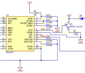
I can't understand what exactly I'm doing wrong to not get a stable current output with the expected DAC codes. I'd be very grateful for any suggestions.

Best regards,
Gaurav

  • Hi Gaurav,

    There are several things unclear.  One thing is your are powering the PGA305 from a supply independent from the loop source.  Is this source able to handle the current requirements and stability needs of the circuit.  PWR directly powers the output buffer driving the transistor. 

    Also, how have you connected the COMP pin?  This pin should connect at R5 junction to GND.

    Lastly it is unclear how you are monitoring the current.

    Have you attempted to make the same configuration and measurement on the PGA305EVM to see how it compares to your measurements?

    Best regards,

    Bob B

  • Dear Bob,

    I am powering via a 3.3V LDO with max 100mA output and use ceramic caps as recommended by their datasheet. The LDO Vin pin has a 150 ohm passive current limiting resistor connecting it to LOOP+.
    If you feel it could be a cause, I can try cutting the PWR trace and connecting it to LOOP+.

    The COMP pin goes to the GND plane with a via, the same as R5. Is it required to connect COMP to GND specifically at the R5 junction?

    For the current monitoring, I have a Keysight 34465A DMM in series with the power supply and this application board.

    I have a PGA300EVM and tried using the PGA305 with the PGA305EVM GUI software and the jumpers set  to current mode with I2C (table 2 on page 7 of the PGAxxxEVM-034 user guide SLDU011B). 
    However, the IC does not respond to I2C commands despite the GUI showing hardware connected.
    Next, I moved the jumpers to table 3 for the OWI interface and the GUI does connect successfully. 

    The whole time the current value is 22mA even if I configure the DAC register to enable 4-20mA. Changing the DAC_REG0 registers has no effect.
    Also, even if I click 'Unlock EEPROM', I cannot write to any EEPROM address such as the IIR filter values and reading the EEPROM gives me all zeros.

    Regards,
    Gaurav.

  • Hi Gaurav,

    The PGA305 has internal LDOs, so you really don't need to have an external LDO.  There could be some issue here, but it is difficult to say. 

    The I2C mode should work fine as that is what I use all of the time, but to set the registers you need to be in digital interface mode and not compensation mode (which is the default startup) (upper left button in the GUI).

    Regarding the current mode using the EVM, the default configuration is for voltage output mode.  You need to correctly follow the user guide jumper settings and correctly set the hardware configuration to current output mode.

    Best regards,

    Bob B

  • Dear Bob,

    In my application, I am using the external LDO as I have another microcontroller on the board that also requires 3.3V.
    On my target microcontroller, I2C communication with the PGA305 works perfectly and I can read and write registers/EEPROM correctly.
    The issue only remains that the DAC output current is not being observed for the appropriate DAC_REG0 register value.

    On the PGA305EVM, I am powering it with a 24VDC supply and have set the jumpers correctly to current output mode with I2C as listed in the manual.

    It fails to communicate over I2C but does connect in OWI mode.
    Clicking the digital interface mode button doesn't have any effect. Is the digital interface mode not accessible over OWI?

    Regards,
    Gaurav.

  • Hi Gaurav.,

    There should be not be an issue with current output mode affecting the I2C communication. Make sure you are not in Compensation Mode. The button at the top-left of the GUI must show Digital interface and the I2C button should be highlighted as the communication method.  Also make sure that the status at the bottom of the GUI shows HW CONNECTED  and a green box at the upper right shows DI Active.

    OWI should also work, so if neither I2C or OWI are working, then I suspect that there is an issue with the GUI communication to the EVM through the USB2ANY interface.  You can monitor the communication at the designated test points along the edge of the EVM connector to the USB2ANY.

    Best regards,

    Bob B