This thread has been locked.

If you have a related question, please click the "Ask a related question" button in the top right corner. The newly created question will be automatically linked to this question.

IWR6843AOP: capon phase compensation

Part Number: IWR6843AOP

HI

 Dear TI engineers,I‘m learning the 3D_people_tracking project,in the source file radarProcess.c,I found the code as follows:


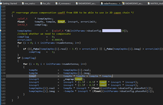
the note is 'rearrange phase compensation coeff from OOB to be able to use in 2D capon chain', how to understand the phase rearrange which can be used in the capon steering,is there any math theory?

Why is the antenna calibration coefficient compensated in advance on the steering vector, and perform the conversion as shown in the figure above

BR,

wenhong Liu.

  • Hi, 

    An expert will comment shortly.

    Best,

    Nate

  • Hi,

    This just multiplies the antenna phase vector compensation factors (from the compRangeBiasAndRxChanPhase CLI argument) and multiplies them by the expected phase differences due to the feed lines from the antennas to the IC (from the Pcount3DDemo_CLIBoardAntPhaseRot CLI argument) for a single multiplication factor.

    Best,

    Nate

  • Hi,

    I have a few more questions here, can you explain to me the meaning of line from 139 to 142 in the picture above? My understanding is that using 0 degree calibration, what we can get is a vector of compensation coefficients. When using DBF Angle measurement, the coefficient can be multiplied directly over the steering vector or directly over the antenna data vector. However, when capon is used for Angle measurement, the covariance matrix composed of antenna data will be inverted. At this time, if the calibration coefficient is directly multiplied on the steering vector, I think it will cause problems, because it is not a linear operation like DBF Angle measurement.

    BR,

    wenhongLiu.


  • Hi,

    The inversion of the covariance matrix will happen after the input data is multiplied by the compensation coefficients, which is then multiplied by the expected phase differences due to the feed lines from the antennas to the IC. This resultant vector will be used to calculate the covariance matrix. The steering vectors are not relevant here yet because they will be used later, after the covariance matrix has been calculated (steering vectors are v) in picture below from https://en.wikipedia.org/wiki/Sensor_array

    Best,

    Nate

  • Thanks,I got it. I mistakenly assumed that the compensation coefficients was multiplied by the steering vector.