This thread has been locked.

If you have a related question, please click the "Ask a related question" button in the top right corner. The newly created question will be automatically linked to this question.

AWR1843: How to enable 4byte Addressing mode awr1843 for MX25L25645G (mmwave_sdk_03_05_00_04)

Part Number: AWR1843
Other Parts Discussed in Thread: MMWAVEICBOOST

I have connected FLASH MX25L25645G to my AWR1843. I want to access whole 64MB (512Mb) of flash. In am able to access only 16MB out of 64MB. After the RCA I found out that it is because of the 3 Byte Addressing mode.

In order to enable 4 Byte addressing mode I tried the following methods.

1. I tried to enable the 4Byte addressing mode using EN4B(0xB7). 

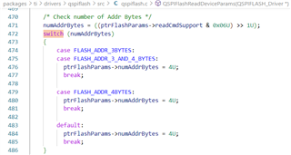
2. Tried setting the numAddrBytes to 4U by Default.

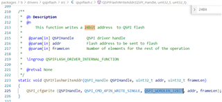
3. change the QSPI_WORDLEN_24BIT to QSPI_WORDLEN_32BIT 

Can you please suggest me the way I can be able to enable the 4Byte addressing mode or any other way to access the 64MB Flash.

Note:
SDK Version: mmwave_sdk_03_05_00_04
I have build the driver after making all the above changes through the makefiles (make drv).

  • Hey Manoj,

    First of all, I had few questions I wanted to access to get a better idea of what you're doing so far:

    1. How are you initializing and opening the driver?
    2. Are you using a modified version of an existing TI AWR1843 demo or is this for a project made from scratch? 
    3. How have you verified the accessible memory?

    If you haven't seen it already, I would recommend looking over the QSPI flash driver documentation located under <MMWAVE_SDK3_VER>\packages\ti\drivers\qspiflash\docs, specifically the index.html file, to see a brief overview of how to use the driver. Additionally, the test code found in the driver test folder, <MMWAVE_SDK3_VER>\packages\ti\drivers\qspiflash\test\common\test_common.c, shows many different ways of configuring the flash driver to read and write. 

    Regarding recompiling the driver, did you recompile after changing the setenv.bat file to use set MMWAVE_SDK_DEVICE=awr18xx? If you have a MMWAVEICBOOST, you can also debug your project in Code Composer Studio and see if your project is linked to the updated QSPI flash driver library.

    Hopefully, this gave you a few new resources to start looking into, but please let me know if you need more assistance.

    Regards,

    Kristien 

  • Dear Kristien,

    1. How are you initializing and opening the driver?

    uint32_t QSPIFlash_Init(void)
    {
        int32_t retVal = 0;
        QSPI_Params QSPIParams;
    
        /* Setup the PINMUX to bring out the QSPI */
        Pinmux_Set_OverrideCtrl(SOC_XWR18XX_PINR12_PADAP,
                                PINMUX_OUTEN_RETAIN_HW_CTRL,
                                PINMUX_INPEN_RETAIN_HW_CTRL);
        Pinmux_Set_FuncSel(SOC_XWR18XX_PINR12_PADAP,
        SOC_XWR18XX_PINR12_PADAP_QSPI_CLK);
    
        Pinmux_Set_OverrideCtrl(SOC_XWR18XX_PINP11_PADAQ,
                                PINMUX_OUTEN_RETAIN_HW_CTRL,
                                PINMUX_INPEN_RETAIN_HW_CTRL);
        Pinmux_Set_FuncSel(SOC_XWR18XX_PINP11_PADAQ,
        SOC_XWR18XX_PINP11_PADAQ_QSPI_CSN);
    
        Pinmux_Set_OverrideCtrl(SOC_XWR18XX_PINR13_PADAL,
                                PINMUX_OUTEN_RETAIN_HW_CTRL,
                                PINMUX_INPEN_RETAIN_HW_CTRL);
        Pinmux_Set_FuncSel(SOC_XWR18XX_PINR13_PADAL,
        SOC_XWR18XX_PINR13_PADAL_QSPI_D0);
    
        Pinmux_Set_OverrideCtrl(SOC_XWR18XX_PINN12_PADAM,
                                PINMUX_OUTEN_RETAIN_HW_CTRL,
                                PINMUX_INPEN_RETAIN_HW_CTRL);
        Pinmux_Set_FuncSel(SOC_XWR18XX_PINN12_PADAM,
        SOC_XWR18XX_PINN12_PADAM_QSPI_D1);
    
        Pinmux_Set_OverrideCtrl(SOC_XWR18XX_PINR14_PADAN,
                                PINMUX_OUTEN_RETAIN_HW_CTRL,
                                PINMUX_INPEN_RETAIN_HW_CTRL);
        Pinmux_Set_FuncSel(SOC_XWR18XX_PINR14_PADAN,
        SOC_XWR18XX_PINR14_PADAN_QSPI_D2);
    
        Pinmux_Set_OverrideCtrl(SOC_XWR18XX_PINP12_PADAO,
                                PINMUX_OUTEN_RETAIN_HW_CTRL,
                                PINMUX_INPEN_RETAIN_HW_CTRL);
        Pinmux_Set_FuncSel(SOC_XWR18XX_PINP12_PADAO,
        SOC_XWR18XX_PINP12_PADAO_QSPI_D3);
    
        /* Initialize the QSPI Driver */
        QSPI_init();
    
        /* Initialize the QSPI Flash */
        QSPIFlash_init();
    
        /* Open QSPI driver */
        QSPI_Params_init(&QSPIParams);
    
        /* Set the QSPI peripheral clock to 200MHz  */
        QSPIParams.qspiClk = 200 * 1000000U;
    
        /* Running at 40MHz QSPI bit rate*/
        QSPIParams.bitRate = 40 * 1000000U;
    
        QSPIParams.clkMode = QSPI_CLOCK_MODE_0;
    
        gQSPIDrv = QSPI_open(&QSPIParams, &retVal);
    
        if (gQSPIDrv == NULL)
        {
            //printf("QSPI_open failed with error=%d\n", retVal);
            return 0;
        }
    
        QSPIFlashHandle = QSPIFlash_open(gQSPIDrv, &retVal);
    
        if (QSPIFlashHandle == NULL)
        {
            //System_printf("QSPIFlash Open API ", MCPI_TestResult_FAIL);
            return 0;
        }
    
        return 1;
    }
    2. Are you using a modified version of an existing TI AWR1843 demo or is this for a project made from scratch? 

    I'm using modified example from automotive toolbox (medium range radar).

    3. How have you verified the accessible memory?

    I have written some dummy data and read from the same locations. I'm getting only 16MB of valid data, after that the data is overwritten from 0-16MB.

    During the recompilation of the driver i'm running ./setenv.bat file to using set MMWAVE_SDK_DEVICE=awr18xx. I'm able to build the "lib/libqspiflash_xwr18xx.aer4f".

    Moreover, if you can guide me how can i run unit tests on newly build driver.

  • Hey Manoj,

    I will need another day or two to look more into the code you provided and the medium range radar project you are building off of to see if there is any issues. For now, if you would like to run the unit tests for the QSPI flash driver, you can use the xwr18xx_qspiflash_mss.xer4f file located under <MMWAVE_SDK3_VER>/packages/ti/drivers/qspiflash/test/xwr18xx and load it onto the device using the CCS debugger.

    You will need a MMWAVEICBOOST to see any of the test outputs in CCS and will need to flash the CCS debug binary, xwr18xx_ccsdebug.bin, located under <MMWAVE_SDK3_VER>/packages/ti/utils/ccsdebug before loading the program. You can also build the binaries yourself using the instructions outlined on p. 42 and 43 of the MMWAVE SDK User Guide (<MMWAVE_SDK3_VER>/docs/mmwave_sdk_user_guide.pdf).

    Note: the test binary is unlikely to work for your flash device without modifications which is why I would recommend using it as reference instead. 

    Once again, please give me a day or two to look more into issue. I will reach out to you once I have more information, but let me know if you have any other questions related to this issue.

    Regards,

    Kristien