This thread has been locked.

If you have a related question, please click the "Ask a related question" button in the top right corner. The newly created question will be automatically linked to this question.

IWR6843AOP: Radar Performance Improvement on custom board

Part Number: IWR6843AOP

Hi IWR6843AOP Champ

My customer manufactured a custom board using IWR6843AOP, and two AOPs are mounted on one board as shown in the picture below.
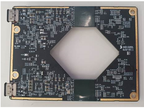
Firmware : "area_scanner_68xx_demo_aop.bin"

Chirp config : "area_scanner_68xx_AOP.cfg"

Visualizer : "area_scanner_visualizer.exe"

SDK : 'mmwave_sdk_03_06_00_00-LTS"

Toolbox : "radar_toolbox_1_00_00_26" 

Test Result : 

Radar device, located at the top, outputs the point cloud to a satisfactory level during cfar detection, and tracking works well for people.

However, the radar located at the bottom does not output the point cloud normally, and the human tracking results are not satisfactory.

As the distance between the human and radar increases, or the angle is closer to +-60 degrees, the point cloud is hardly output. Moreover, in the +-60 degree interval, people tracking rarely works.

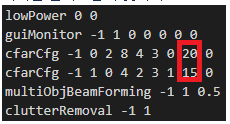
Among the following chirp configurations, we observed that lowering the <thresholdScale> parameter value of cfar in first & second alleviates symptoms. The amount of point cloud increases, but it is not satisfactory. i.e. 20->13, 15-> 8
Can you please give us any helpful guidance to figure out the cause of the problem?

Also we also need your kind help to improve the performance of the bottom side radar device.

  • Hello,

    Is there any difference between chirp parameters being sent to the top and bottom chips? In terms of chirp design? From a software point of view, if you have two chips close to each other similar to what your picture shows, and flash the same firmware and chirp config, there shouldn't be any performance differences. Or at the very least anything as drastic as what you are claiming. If reducing SNR helps but isn't satisfactory, and you have to reduce it as drastically as you are showing, then for whatever reason your signal being reflected back from targets are very different from the top sensor. Has there been any hardware tests done?

    Best Regards,

    Pedrhom

  • Hi Pedrhom 

    Thanks for your kind answer.

    Customer sent us the images for test setup as below.

    * Test Setup

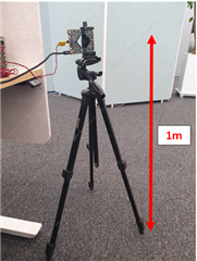
    - FOV(Field of View) of Target : 30~120degree, 5m distance from sensors.

    No obstruction within FOV area

    Sensor angle facing front perpendicular to floor

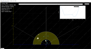
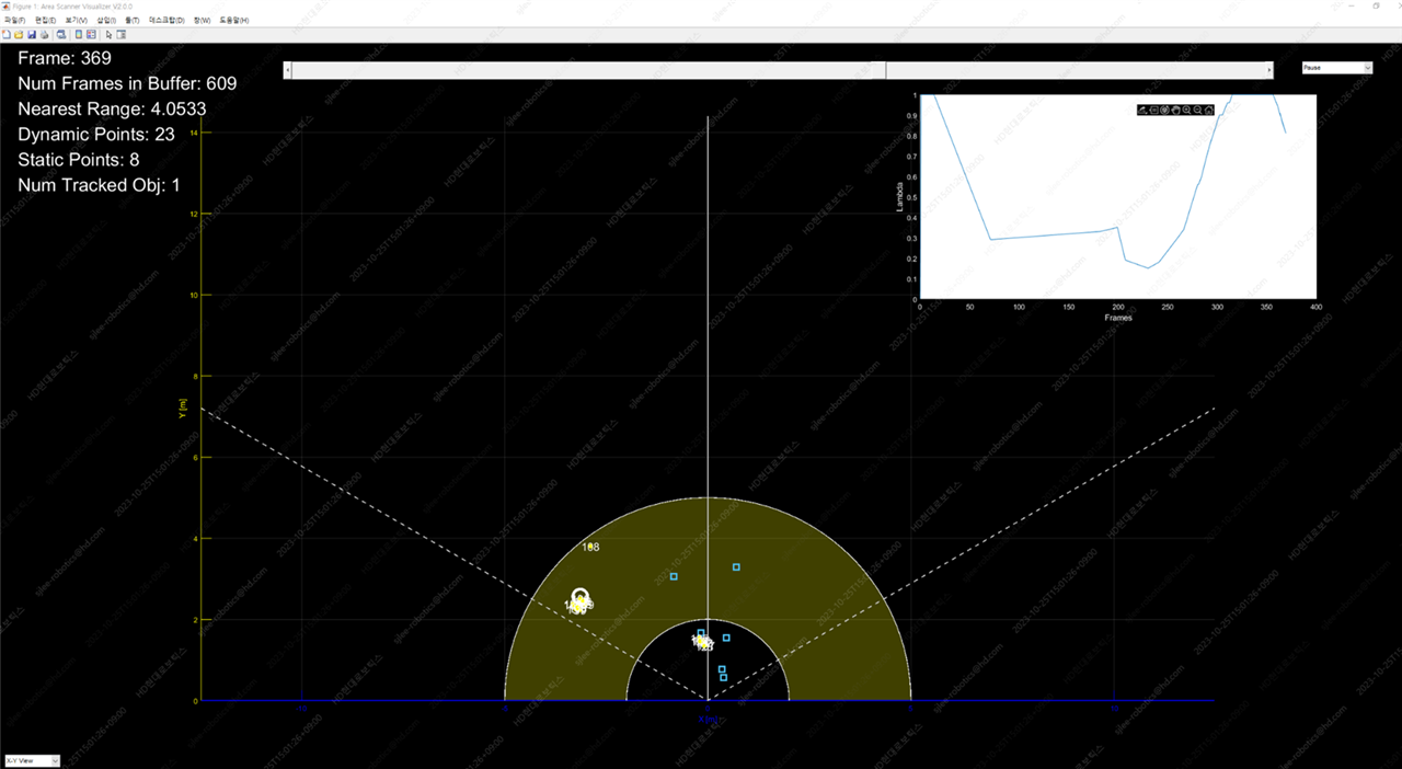
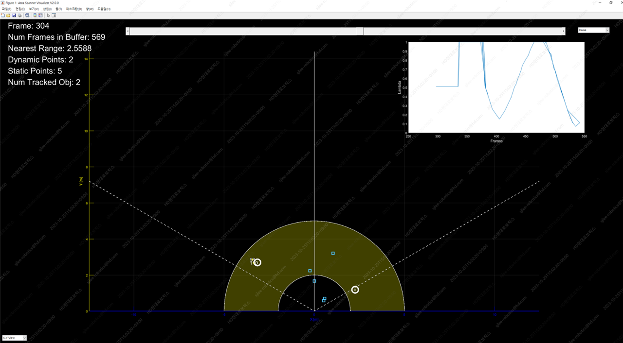
    * Test Result #1

    - Person tracking results from the sensor located at the top
    - Yellow dots correspond to point clouds and white circles correspond to human tracking results
    - The figures on the yellow dots are SNR values
    - Even if a person's location approaches 120° and 5, a large cloud of points is created and people's tracking is not to be missed

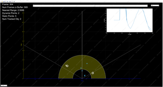
    * Test Result #2

    - Person tracking results from sensors located at the bottom
    - Yellow dots correspond to point clouds and white circles correspond to human tracking results
    - The figures on the yellow dots are SNR values
    - The closer a person is to 120° and 5m, the less likely the point cloud is to be created and the less likely it is to track people

    - Signal Noise (SNR) of points that generate human tracking The Ratio) value is similar in size to around 100 for both sensors.

    - The firmware programmed on both radiacs is the same.

    What advice would you give to make it conditions for both ICs to have almost similar performance? Please advise me if you have any good ideas.

    Thanks.

    BR. Jack

  • Hello,

    Please give me until early next to have potential problems that could be looked into.

  • Hello,

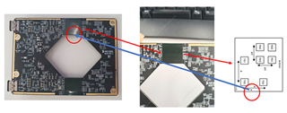
    First question: what is the polarization of each chip? Are their A1 locations the same for both, it is hard to see due to low picture quality. Having one chip be backwards could cause detection issues. Second question: have there been tests when rotating the test board by 90 and 180 degrees? Does the underperforming chip change when the board is rotated?

    Best Regards,

    Pedrhom

  • Hi 

    Attached figures again. and waiting for answers from customer regarding your questions.

    * Upper sensor

    * Bottom sensor

  • Hello,

    I will wait for your response

    Best Regards,

    Pedrhom

  • Hi Pedrhom

    Please see the polarization of the MMICs installed on the PCB. They have both same direction. 

    Let's wait a bit more they will give us test result by rotating angle.

    Thanks.

    Regards, 

    Jack

  • Hello Jack,

    It is good that the polarization direction is the same for both, I will wait for test results on point cloud performance between the two chips based on hardware angle orientation rotated 90 degrees and 180 degrees.

    Best Regards,

    Pedrhom