


Other Parts Discussed in Thread: IWRL6432
如下所示,我设置profile0,Tx0和Tx1的相位都是0,然后下面chrip使用profile0,设置chrip开始和结束都是0.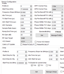 然后设置profile1,Tx0和Tx1的相位是0,180,然后下面chrip使用profile1,设置chrip开始和结束都是1,
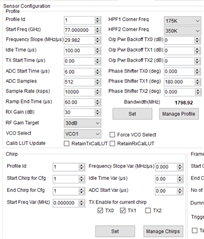 最后frame设置为这样
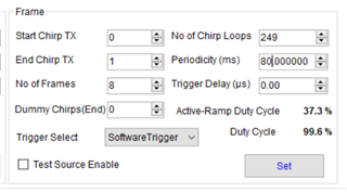 这样理论上也是可以实现BPM的对吧
如下所示,我设置profile0,Tx0和Tx1的相位都是0,然后下面chrip使用profile0,设置chrip开始和结束都是0.然后设置profile1,Tx0和Tx1的相位是0,180,然后下面chrip使用profile1,设置chrip开始和结束都是1,最后frame设置为这样这样理论上也是可以实现BPM的对吧

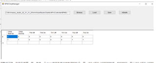 在结果可视化的时候出现了下面的问题,
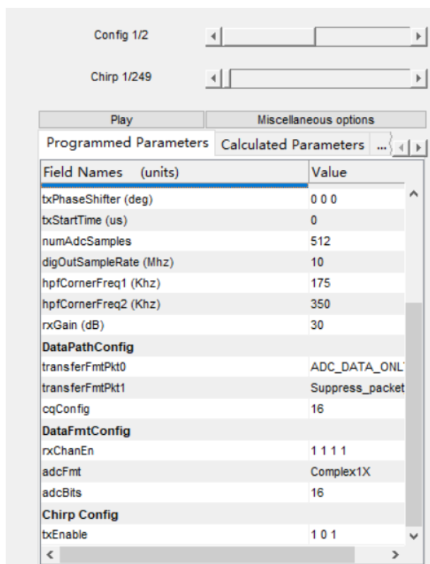
 可以看到这个最上面一行相位都是0,0,0,没有反向。
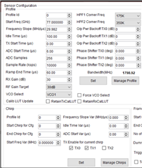 Then set the phase of profile1, Tx0 and Tx1 to be 0, 180, then use profile1 for the following chrip, set the chrip to start and end with 1,
 The final frame is set to this
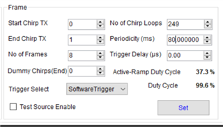 This is also theoretically possible to implement BPM, right?
 The following problem arose when visualizing the results
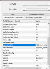 You can see that the top row is all phase 0, 0, 0, no inversion。By the way, when I implement BPM mode, does the position of the two antennas used matter? If I want to use three antennas to simultaneously transmit signals to achieve BPM, how can I achieve this?
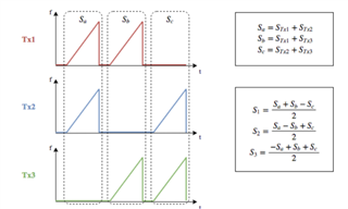 here is my code to decode.