This thread has been locked.

If you have a related question, please click the "Ask a related question" button in the top right corner. The newly created question will be automatically linked to this question.

TDC1000-C2000EVM: TOF measurement constant regardless of transceiver distance

Part Number: TDC1000-C2000EVM
Other Parts Discussed in Thread: TDC1000, , TUSS4470, MSP430FR6047

Hi,

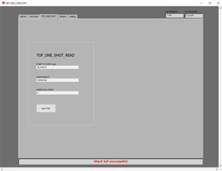
I'm using working on using the TDC1000-C2000EVM to evaluate the TDC1000. Our end goal is to use it for volume (from the top of the container down) and/or flow measurements for water. The transceiver we're using is a 1MHz transceiver - H2KMPYA1000600 from Unictron.  Before doing our more targeted experimentation, I'm making sure that I can run and understand how the board and GUI work. I'm running into an issue where no matter how far away from a surface I place the ultrasonic transceiver, the TOF in the GUI is constantly reading ~38.5us. I can have the transceiver pointing at the ceiling or directly on my desk surface and the TOF does not change.

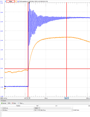
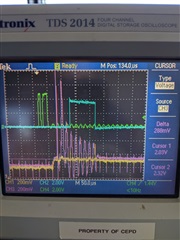
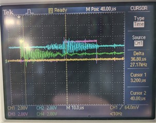
This is what I'm seeing on the scope. Yellow is START, pink is STOP, green is the signal at TX1, and blue is the COMPIN buffer.

Here are the settings that are currently set. 

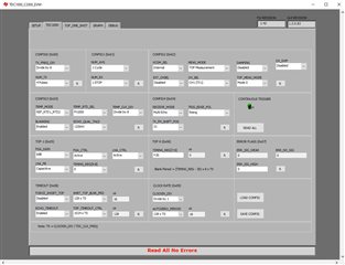
I've tried setting the autozero period to 512xT0 or 64us to avoid all ringing from the TX, but nothing is then ever received at any distance. I'm at a loss at to what needs to change to correctly see the TOF. Is there a setting that is wrong somewhere? Any guidance would be appreciated to help keep this design moving forward.

Thanks,

Tim

  • Hi Tim,

    From your configuration, it looks like you will need to add more time to the auto zero period.  Your transmit to echo listen time is around 36uS, so you are still picking up the ringing from the transmit, which immediately triggers the STOP. 

    A few other items.

    1. Air is not a good medium for 1MHz transducers.  The signal will attenuate greatly in air.  4 pulses will not really be suitable for any range in air.  You could increase the number of pulses and RX gain, but I think your results will pretty unusable at most distances. I recommend mounting the transducers to the bottom of the tank using water as the medium as shown in the guide below for better results.

    https://www.ti.com/lit/an/snaa266a/snaa266a.pdf     

    2. We do not recommend the TDC1000 for flow measurement applications as there is an issue where the first zero crossing can be missed and not trigger until the next crossing, which causes a error in the flow rate measurement.  This does not affect the level sensing use case.    

  • 1. Unfortunately, we don't have a choice but to mount the transducer at the top. We'll look into some lower frequency options and modify the eval board to work with them.

    2. I'd seen mention of this, but also that doing an averaging of readings could help alleviate this. How big of an error could be caused by this? Our use case doesn't need too high of an accuracy. Depending on the size of the error, we can also implement software that would detect the erroneous reading and disregard it.

  • Tim,

    I am currently doing some testing with the transducer mounted at the top of a container using a 200kHz transducer and TUSS4470.  I can update you here when I have some results in the next few days.   

    See the post below.  The issue is at zero or low flow rates, the first stop can be missed, causing the ToF error to be off by a cycle, so the frequency will also affect the error.  If you will not be operating at low flow rates, this may be acceptable for your application with averaging and detecting/removing errors.  

    (+) TDC1000: How to improve accuracy of flow measurement using TDC1000 & TDC7200 in flow meter application - Sensors forum - Sensors - TI E2E support forums

  • Hi Eddie,

    We'll be working with low flow, so we'll look into an alternate part for the flow.

    For the level sensing, I've modified our board to work with a 58kHz transducer we have on hand, with a 16.9kHz to 338.6kHz bandpass filter on the receive. I was still seeing some significant ringing that was being picked up as soon as the listen time starts, even out to a millisecond. This looks to be an issue with the transducer (CUSA-TR50-05-2000-W68) as I see it has a 25cm minimum distance. To get around this I'm trying to use a separate Tx and Rx transducer in Mode 1 transmitting on Tx1 and receiving on Rx1. Would this help deal with the transmit ringing, as the Tx and Rx lines are no longer tied together?

    I'm still seeing the same issue of the stop triggering immediately when the listening starts, no matter how far apart the two transducers are, even when they're a foot apart and facing opposite directions. Could there be issues with crosstalk between the two?

  • Tim,

    For low flow rates, I recommend the MSP430FR6047.  

    Yes, using two transducers will reduce the length and amplitude of the ringing seen on the RX, but you would still see some ringing from the internal crosstalk inside the device.  You can also use a lower number of pulses to help reduce ringdown.  To really eliminate the ringing on the RX, you would need to use 2 separate TDC devices.  

    58kHz may be to low of a transducer frequency depending on your minimum/maximum distance and resolution requirement.  100kHz to 400kHz will have a shorter ring down period and higher measurement resolution, but lower maximum distance.  I am currently testing with the SMATR200H19XDA 200kHz transducer using the TUSS4470.  Ringdown is on the order of about 200uS with this transducer.  Image below shows the excitation pulses and ringdown.  


     Your immediate STOP assertion could possibly be crosstalk.  Can you show how you have the transducers connected?   

  • Our maximum range is 20-25cm.The minimum we're aiming for is as close to 0cm as possible.

    For the transducer connection, we've soldered on some jumper cables that plug directly into the TDC1000-C2000EVM. 

  • Thanks Tim.  Could you also show the oscilloscope shot with the COMPIN signals, and STOP signal?  It would also be useful to put markers for VCOM and the set threshold level similar to the image below.  The threshold is set referencing VCOM.  I would like to be sure that there is not a valid threshold crossing.  If there is a valid crossing, you may just need to change the threshold configuration.

  • From the oscilloscope, it is passing the set threshold. I can increase the threshold value, but then no receive signal is ever received. At one point during testing I disconnected the Tx transducer, and I was still seeing the same receive signal, so I'm not sure where the receive signal is coming from. It definitely isn't from the Tx signal though.

  • Tim,

    Depending on the mode that you are using, you may need to configure the hardware differently.  In the schematic below, you will see that TX1 is also connected to RX2 through R81 and TX2 connected to RX1 through R80.  The modes and respective TX/RX signals used are shown in section 8.4 of the datasheet as well as below.  The R80 and R81 0 ohm resistors can be removed if needed for your mode of operation.