This thread has been locked.

If you have a related question, please click the "Ask a related question" button in the top right corner. The newly created question will be automatically linked to this question.

AFE3010: communication to a host MCU on the isolated side

Part Number: AFE3010

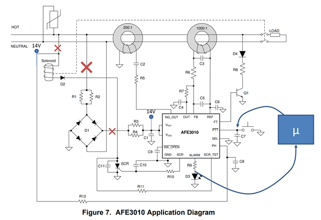
Does AFE3010 operate normally if all connections to the line are interrupted? The power for the AFE3010, shown in the diagram as a 14VDC source, would come from the cold side, where the microcontroller unit sits. The only connection to the power line would be isolated through the current transformers. Below is a rudimentary diagram. Red crosses show where connections are eliminated:

The idea is to save cost in the system by reducing the number of optoisolators. Can you please comment? 

Thank you!

  • Hello Lenio,

    1. The PH pin must have a 50% duty cycle, ~60-Hz signal going between at least or beyond GND to VDD. The PH pin is essentially the clock of the device. The PH pin does have clamps to internal rails so I would think you could still connect this to LINE with a 1MΩ resistor and it not pose an issue of isolation because any current is limited to micro amps.

    2. The SCR_TST pin must also be seeing a half-wave rectified line voltage  in order to satisfy it internal watch dog timer, which is part of the self continuous test. Once again, I would think R11 could still provide significant limiting to remove need for an optoisolator.

    Although this brings up next consideration: Is the SCR self-test going to be required or is SCR even going to be used at all? If an SCR is not going to be used to pull current through solenoid, then you do not need the SCR self test so you can set SEL to GND and you can increase R11 to a comfortably high 1MΩ.

    If an SCR is going to be used, then R11 cannot exceed 68 kΩ or else this would interfere with SCR self test.

    3.The AFE3010 should still power up with a 14V source although there will be some performance degradation because the internal Zener regulator has a break down of 20-V. This 20-V regulator then feeds the internal 5V LDO responsible for the internal logic. While this seems like plenty of headroom, the downstream circuitry will need to draw more current from the 14-V source because the 20-V regulator is not optimally biased. Transient power surges (firing SCR, powering D3, and driving current from NG_OUT pin into C2) may require more current than characterized and thus may stress the external 14-V source. This should be validated with an EVM.

    Another downside to the 14-V source is that you will lose some strength in the detection capability of neutral-to-ground faults. The N-G fault detection relies upon driving large current into the 200 turn coil using a half-bridge driver pulled up to VDD. A smaller VDD voltage across C2 means less current, which means a smaller signal. This would also need to be validated.

    I highly recommend testing this with an EVM to make sure no significant performance is lost as the EVM is highly configurable.

    Hope this helps.

    Best,

    Peter

  • Peter, thank you so much for the thorough answer - this is very helpful! I'll open another thread if I happen to have follow up questions.