Hi Team,
When using the AWR2243 2-chip cascaded board, there is one behavior:
When the radar is placed in a high and low temperature tank, abnormal numbers of applications occur after the radar is started, the master and slave chip acquisition times are inconsistent, and the CP data is incorrect.
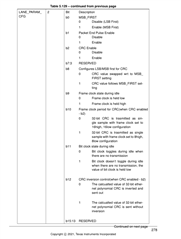
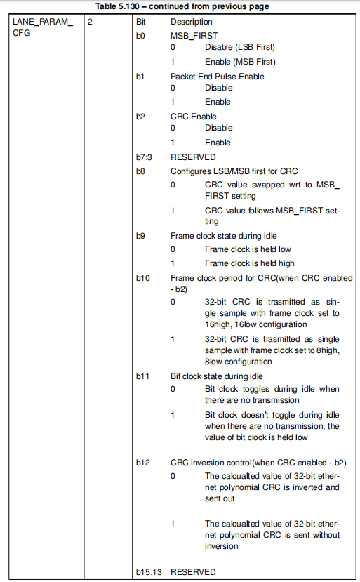
So the customer would like to check the correctness of LVDS data. The CRC on LVDS in the Interface_control document is described only as follows, which is a little confusion regarding the configuration of each bit, and the ADC cannot capture data in certain configurations, such as bit8/ 9/10 /11 being set to 1. And the customer would like to figure out where the CRC is being used and make sense.
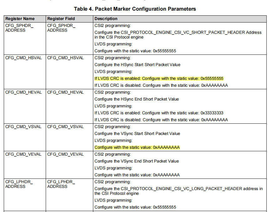
In the AWR16XX &AWR22XX data path, there is a description of the LVDS CRC as shown in the figure below, which requires register configuration of the information. Regardless of which CRC mode is selected as described in the figure below, could you help share how to configure the CFG_CMD_HSVAL, CFG_CMD_VSVAL, link list, LVDS frame CRC and more? Is the interface open to the user?
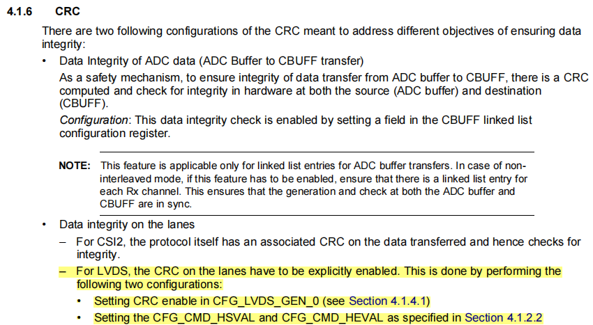
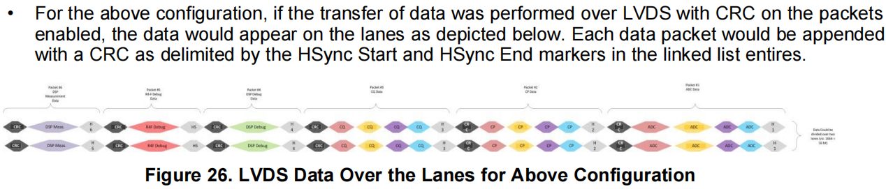
If all of the above are configured successfully, will the CRC message be shown on the LVDS signal transmitted by the sensor to the external host? Or is the CRC only can be seen on the chip's internal ADC buffer to CBUFF link? How can the user see the CRC information?

Could you help check this case? Thanks.
Best Regards,
Cherry