Hello,
I have some questions about CQ and LVDS CRC.
1. What is the relationship between the value of CQ1 and the value in AWR_RF_DFE_STATISTICS_REPORT_SB? Can these two values be converted to each other?
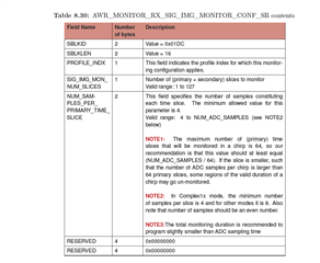
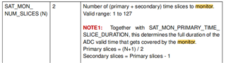
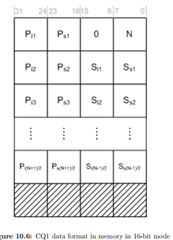
2. CQ1 is the power value of signal and image. Slice number must be set as singular or both singular and even? Because I see the Primary slice =(N+1)/2, secondary slice= (N-1)/2, if N is even, What is the value of slice number? The length of CQ1 and CQ2 are fixed at 32 Bytes. When I set my slice to 16, I see an effective value of 8 bytes, corresponding to 4 slices. For example, one byte value is 0XAF, the corresponding power is 175* (-0.5dBm) =-87.5dBm. But when I set my slice to 15, I only see an effective value of 6 bytes of RX0, corresponding to 3 slices, and then all zeros; I can see an effective value of 8 bytes in nRX1/2/3.
Why is it a fixed length? I understand there should be a total of slice*2 bytes.
What means are those "effective values" ? Is the power calculation correct?
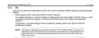
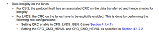
3. I can configure LVDS CRC enable , but I don't know where I can see CRC data. Is it added at the end of normal LVDS to transmit to the external host or just a internal data in chip between ADC buffer and CBUFF that user can't read ? In the AWR16XX and AWR22xx data path document, I see some description about CRC register, but I don't know how use these registers. Actually I think these registers are not configurable. Can you tell me how I can check the LVDS' correction? Beacause I put the RADAR into a High and low temperature box,which six sides are metal inside, my LVDS data is wrong including CQ's configuration value for "N". When I decrease the power of TX or the gain of RX, LVDS data return to normal. I think some scenarios can trigger the LVDS data wrong, can you let me know this infomation and how to deal it?
In addition, I think that theory does not agree with practice about LVDS CRC. Maybe we lack the latest documentation?