This thread has been locked.

If you have a related question, please click the "Ask a related question" button in the top right corner. The newly created question will be automatically linked to this question.

IWR6843ISK-ODS: Seemingly switched Inphase and Quadrature Values

Part Number: IWR6843ISK-ODS
Other Parts Discussed in Thread: DCA1000EVM,

Dear experts,

I have a question regarding the ADC raw data format of the IWR6843ISK-ODS and DCA1000EVM combination with which I am measuring right now. I was doing test measurements in which I walked towards the radar and away from it multiple time. From the measured data I created range plots of the first chirp for every measurement and plotted these over time. (Please click on the picture to get the full resolution version.)

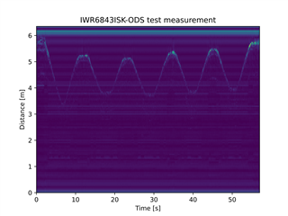
The problem is that the image is seemingly flipped because I was moving at the distance range from 0 to 3 meters. Objects that are close to the radar seem to be far away from the radar (high frequency) and objects that are far away seem to be close (low frequency). I do not use mmWaveStudio but custom made software for the communication with the DCA1000EVM. The only steps after collecting the raw data are deinterleaving the samples and doing a fourier transformation onto the chirps to get the range plots.

Now if I just switch the in-phase and quadrate numbers for each sample, I get the correct representation of the room in front of the radar.


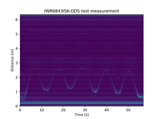
This makes sense if I would have had the I and Q data switched from the beginning (negative frequency from the fourier transform) but I am very sure that I did the deinterleaving as described in the documentation (see below in 'context'; with inphase = the real part, quadrature = the imaginary part).

Is there any configuration that I could have mistakenly done to just change the I and Q raw data sequence? Everything else seems to work as expected.


Context:

  • For my setup I wrote some custom code to send the configuration and starting codes via Ethernet towards the DCA1000EVM and collect raw data from DCA1000EVM.
  • I also used and configured the "Hard Coded Config for OOB Demo" in which I only changed the chirp config files.
  • Right now I am collecting raw data, sorting the ethernet packages into measurements and deinterleaving them similar to what is described here
    - Mmwave Radar Device ADC Raw Data Capture page 10 
    - (or the same information from a different document) mmWave Studio GUI page 80 with "DCA1000 EVM capture format (xWR16xx complex, 4 channel, 2 lanes [Non-24.8Interleaved])" 

Thank you!

  • Hey Lars,

    Thanks for reaching out regarding your question. One of our experts on raw data collection will get back to you within the next 24 hours.

    Regards,

    Kristien


  • I am looking forward to the reply!

    In the meantime I tried making sense of it and can maybe give some additional information.

    The source for my deinterleaving as stated in the original post under 'context' are two documents for mmWaveStudio ('Mmwave Radar Device ADC Raw Data Capture', 'mmWave Studio GUI'). These document focus on the output of mmWaveStudio. Having used my own software to send commands and receive data directly from the DCA1000EVM might use a different data format. This could be caused by changes that I made in the Radar Firmware or the commands that I send to the DCA1000EVM. Changing these parts might void the validity of the documentation in the mmWaveStudio files.

    I could just accept that the documentation does not fit my setup anymore but I would like to understand which parameters make the difference here so that I dont get any unforeseen wrong data in the future.

    What I changed in the radar firmware and by sending commands to the DCA1000EVM are the following:

    • The changes to the firmware that I did on the "Hard Coded Config for OOB Demo" were only done in the two files which I put into the attachments ('hc_config_defs.h' , 'hc_config_profile_3d.h' in the folder 'mmwave_sdk_68xx_hcc_mss\mss'). The variables from these are explained in the MMWAVE SDK User Guide from page 14. In the file 'hc_config_defs.h' there is actually a variabel 'ADCBUF_HCC_SAMPLE_SWAP' (called '<SampleSwap>' in the MMWAVE SDK User Guide) which could have changed the sequence if inphase and quadrature data.
    • For the direct commands and received data from the DCA1000EVM I used the CLI Tool and specifically the 'DCA1000EVM CLI Software Developer Guide'. I have attached the commands send by me to the DCA1000EVM as 'cf.txt' in the format in which they are explained in the 'DCA1000EVM CLI Software Developer Guide'. For receiving the data page 78 and 79 of the 'DCA1000EVM CLI Software Developer Guide' are important. Here the sequence of the inphase and quadrature numbers would be correct in context of what I have set in the radar firmware but the sequence of the interleaved RX antennas are not fitting to what I get.

    hc_config_profile_3d.h        hc_config_defs.h

    {
      "DCA1000Config": {
        "dataLoggingMode": "raw",
        "dataTransferMode": "LVDSCapture",
        "dataCaptureMode": "ethernetStream",
        "lvdsMode": 2,
        "dataFormatMode": 3,
        "packetDelay_us": 80,
        "ethernetConfig": {
          "DCA1000IPAddress": "192.168.33.180",
          "DCA1000ConfigPort": 4096,
          "DCA1000DataPort": 4098
        },
        "ethernetConfigUpdate": {
          "systemIPAddress": "192.168.33.30",
          "DCA1000IPAddress": "192.168.33.180",
          "DCA1000MACAddress": "12.34.56.78.90.12",
          "DCA1000ConfigPort": 4096,
          "DCA1000DataPort": 4098
        },
        "captureConfig": {
          "fileBasePath": "/home/pi/Desktop/REMUS",
          "filePrefix": "adcdata",
          "maxRecFileSize_MB": 1024,
          "sequenceNumberEnable": 1,
          "captureStopMode": "bytes",
          "bytesToCapture": 128,
          "durationToCapture_ms": 4000,
          "framesToCapture": 801
        },
        "dataFormatConfig": {
          "MSBToggle": 0,
          "laneFmtMap": 0,
          "reorderEnable": 1,
          "dataPortConfig": [
            {
              "portIdx": 0,
              "dataType": "real"
            },
            {
              "portIdx": 1,
              "dataType": "complex"
            },
            {
              "portIdx": 2,
              "dataType": "real"
            },
            {
              "portIdx": 3,
              "dataType": "real"
            },
            {
              "portIdx": 4,
              "dataType": "complex"
            }
          ]
        }
      }
    }
    

  • HI, there:

    There are two parameters that affects the raw ADC format. 

    1) Inside mmWave Studio, by default, ADC setting is configured to have I sample first, followed by Q sample.   In addition, the json file used for mmWave studio is C:\ti\mmwave_studio_02_01_01_00\mmWaveStudio\PostProc\cf.json,  Inside reorderEnable is set to 0.   Under these two conditions, the data format matches the format listed in "DCA1000 EVM capture format (xWR16xx complex, 4 channel, 2 lanes", you will have data format as: 

    I1, I2, Q1, Q2, ...

    2) The SDK OOB (out of box) demo only support the adcbufCfg with Q sample first, followed by I sample.  In addition, in the config json file you attached, you have  reorderEnable set to 1.  Therefore, the data is already in the order of complex pairs and in the format below.

    Q1 I1 Q2 I2 ...

    Best,

    Zigang

  • That solved my problem.

    Thank you for the fast help and have a nice weekend!