This thread has been locked.

If you have a related question, please click the "Ask a related question" button in the top right corner. The newly created question will be automatically linked to this question.

DRV411: About the simulation of DRV411

Part Number: DRV411


Dear TI experts,

    I want to use FEM software e.g, ANSYS to simulate closed-loop Hall sensor which is configured with TI DRV411.  And this would be electromagnetic joint simulation, where DRV411 is the simulated by simplorer as  a circuit and the core  coil of the compensation coil are simulated by E&M fields.

However, I don't know how to simulate the behavior of DRV411. Can you experts tell me if there are any ways For example, use its Spice models, etc.

    Besides, do you experts know how to simulate the Hall sensor?

Best regards

Yatao

  • Hello Yatao,

    We do not have a model for the DRV411 and the behavior.  For the magnetics the core size and air gap should give you the magnetic gain per current?  The hall element sensing I do not know how to model but I think knowing the offset and the change of that offset through its operating range would be good.  If there is a specific calculation you need I could help you.  Make sure your hall element can be driven by the DRV411 hall driving pins and meet the requirements for resistance.  

    I would have to think about how I could model the full system very simply.

    Regards,

    Javier

  • Hi Javier,

        Thanks for your reply.

        I wonder if there are no simulation models for DRV411 and the small hall sensor that is driven by 411, then how to perform electromagnetic filed simulations for the whole hall including DRV411, coil, core and the sensor itself by, for example, ANSYS?

        I want to do this EM simulation to see how the stray magnetic field can affect the Hall output.

    Best regards

  • Hello Yatao,

    I normally simulate the core magnetic gain and use the specification of offset gain to determine the error.  Normally if you get 1mT/A gain from your core to the hall element offset would give you the offset error of your measurement.  A stray field would just change that value.  If you simulate your core you will see the added magnetic field from your stay field and use it to calculate that added gain from your hall sensor. 

    For example.  If you have a core that generates a gain of 1mT/A.  And you get a 0.5mT of added field you will get an error in the range of 0.5A.  Because this is a closed loop system this is the additional error you will get from the stray field on top of the offset error of the hall sensor.  

    So your contributor of the stay field will be all dependent on your core design.

  • Hi Javier,

        Sorry this has not solved my problem yet.

        I can understand your simple calculation method for the error in sensed Ip, e.g., primary current.  However, what I am dealing with is not a very simple EM environment and there are high-current  inductors, relays, high-current  conductors on PCB, etc around the Hall.

        In this environment, with your error calculation method, I think it necessary to perform electromagnetic simulations by, for example, ANSY. And I think only with such EM simulations, can the stray fields generated by surrounding devices and influenced by the hall sensor's compensation coil & core be accurately characterized. You see, the compensation coil & core can also affect the stray B at the hall sensor.

        Hence, Javier, as described above, how can I model the DRV411 to simulate the effects of stray fields on Hall's behavior and accuracy? Or, based on your knowledge, are there any ways to simplify the DRV411+hall models to still obtain relatively accurate simulation results?

    Best regards

    Yatao

  • Hello Yatao,

    I will not be able to give you a full model to simulate but from all the modeling I have done the air gap and the core permeability will define the way it deals with the external stray fields.  The reason is the coupling from the primary current and the compensation coil are best when the air gap is the smallest and the core has high permeability.  The external fields couple to the hall sensor through the air gap and this will cause the error.  This is why smaller air gap and higher permeability material will reduce coupling from stray fields.

    Like I mentioned this can be modeled with Ansys and the error can be calculated relative to the core material.

    If needed I can create some simple examples and show you how I would calculate the error.  I will do it in FEMM since it is much simpler and faster.

  • Hi Javier,

        Thank you for your reply.

        Please spare some time to do the FEMM based simulations of closed-loop hall sensor for me. And I wonder for closed-loop hall sensor, how to model the DRV411 and the hall element? I know DRV411 works a bit like a microprocessor.

    Best regards

    Yatao

  • Hello Yatao,

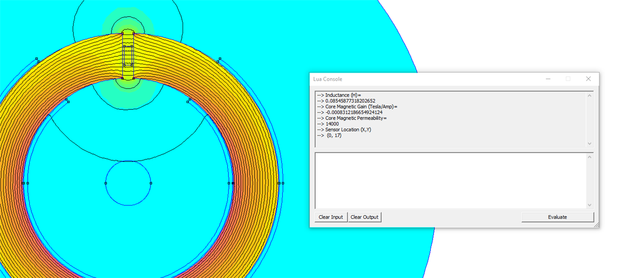
    Here are my simulation parameters.  I changed the airgap and the permeability;  For the hall sensor I only place a measurement point at (0, 17) which is the location of the sensor at it ins not simulated.

    Core Depth: 10mm

    Core Inside Radius 14mm

    CoreOutside Radius:  20mm

    AirGap: 1.5 mm

    Primary conductor Radius:3mm

    Thickness Hall: 1mm

    Length of Hall sensor: 2.5mm 

    Permeability: 14000, 2000

    Number Turns: 1000

    Air Gap =1.5mm

    Magnetic Gain at Hall sensor (center of airgap): 831µT/A (14000), 794µT/A

    Air Gap = 2.5mm

    Magnetic Gain at Hall sensor (center of airgap): 500µT/A (14000), µT/A 484uT/A

    So for exaample if I want to calculate the offset due to the hall sensor I use the following:

    Hall sensor offset =   HW322B(F) (7mV) 

    Sensitibty of 293mV/50mT  (F version is 266 to 320)--> 5.86mV/mT.

    7mV offset  = 1.194mT offset   (this value will be lower if using the current spinning of the DRV411)

    Offset for current measurement = 1.194mT/831µT/A =   1.43A offset measurement.  The higher the magnetic gain the better this value is.

    The reason the magnetic gain matters is also that impacts the external field.  Any offset or extra field will impact the error the same way.

    The next two images are for the magnetic gain calculations:

    Next is the worst case with the magnetic field from a neighbor would only be about 3µT at the sensor from 1A on a conductor close by..  The core diverts the neighboring field away from the hall sensor.

  • Hi, Javier

    Sorry for the delay. I've been very busy and I've been trying to reply you.

    Thank you for your reply.

    Can you please attach the simulation file. Then I can use it to do my simulations.

    Besides, hi Javier, you just ignore the detailed operations of DRV411 and hall element in your FEMM simulations above. Are there really no other ways to simulate DRV411 and hall element in detail? And, is treating them ideally the only way?

    Best regards

    Yatao

  • Hello Yatao,

    I do not simulate the hall element but I assume the hall sensor is in placed in the center of the air gap.  This simulation and adding the hall element offset is what will give you the offset of what you would get.  I used the HW322B offset voltages to calculate the offset above.  I am not sure if you can simulate the errors being compensated for and I think you cannot simulate the errors easily introduced from hall sensors as many things introduce offsets to a hall sensor.  Such as stress and drift.

    Also recall the DRV411 has the current spinning that will reduce the effects of some of the offsets.  So even if you do simulate this may not be as accurate as the DRV411 can produce.

    Attached is the FEMM simulations files

    Regards,

    https://e2e.ti.com/cfs-file/__key/communityserver-discussions-components-files/1023/test_5F00_14000.femhttps://e2e.ti.com/cfs-file/__key/communityserver-discussions-components-files/1023/Test_5F00_14000_5F00_2p5.femhttps://e2e.ti.com/cfs-file/__key/communityserver-discussions-components-files/1023/Test_5F00_2000.femhttps://e2e.ti.com/cfs-file/__key/communityserver-discussions-components-files/1023/Test_5F00_2000_5F00_2p5.fem

    Javier


  • Hello Yatao,

    Hall effect I do not believe can be simulated in Ansys.

    Regards,

    Javier

  • Hi, Javier

    You mean that the hall element and DRV411 can not be simulated in Finite Element Method Simulation software, for example, ANSYS. Hence, we can only do the error calculations like your results given above.  Is my understanding correct?

    Best regards

    Yatao

  • Hello Yatao,

    That is my understanding but I will clarify with our other experts.  I have not done it or needed to do it for application and use of it.

    I also think it will be difficult as a hall sensor would require the excitation and measurement for voltage and then translated back to magnetic field.  It is much easier to place the hall effect sensor and use its specifications.

    Regads,

    Javier

  • Dear Javier,

    Okay, I'll click "This resolved my issue". But when you've clarified with other TI experts, can you please inform me the best and most precise solution?

    Best regards