This thread has been locked.

If you have a related question, please click the "Ask a related question" button in the top right corner. The newly created question will be automatically linked to this question.

TMP1075: Can we use TMP1075 inside a Ring Lug for measuring components upto 90'C temperature in Industrial environment

Part Number: TMP1075
Other Parts Discussed in Thread: TCA9803, TCA9548A, TCA9544A, TCA9517

Hello E2E Sensor Team,

I am looking for your valuable feedback & insights on using the TMP1075 Digital Temperature Sensor for monitoring temperatures in an industrial setting.

Key aspects of our use case include:

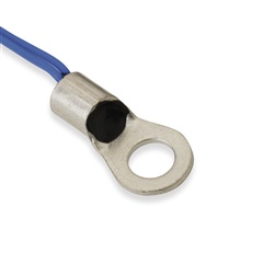
Temperature Components: Monitoring temperatures of outer surface of bearing housing, motor casing, and piston cylinder in Industrial environment using a type of Ring Lug.

Temperature Range: Normal temperatures are below 90°C (for 99% of the lifetime) with occasional peaks up to 120°C, and a AMR of 150°C of the sensor shall always be respected.

System Configuration: We plan to use 4 x TMP1075 sensors, each connected via a 3-meter STP well grounded cable in a star configuration to a single I2C Master on the MCU, operating at/below 5kHz. We intend to use TCA9803 for driving these long cables.

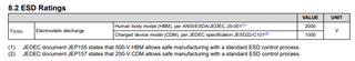
Protection Measures: Implementation of ESD314 for ESD, EFT, and surge protection on both power and data lines. We further plan to use RC filters on the I2C signal lines with 10kHz cutoff frequency.

Sensor Packing: We will create a custom Ring Lug encapsulation for the SOT package on small form factor PCB

Our queries to the Sensor Team:

  1. Is TMP1075 appropriate for our use case? Are we making any obvious mistake here?
  2. Any concerns with using ESD314 for device protection in this setup?
  3. Any feedback on the Star connection, use of TCA9803 in said setup?
  4. If we plan to use a I2C Multiplexer like TCA9548A, how will it impact the drive strength of the TCA9803 for the cables? 

Your guidance will be instrumental in finalizing our design.

Thank you

  • Hi Neet,

    The TMP1075 seems appropriate for your use case in terms of your system requirements considering temperature and interface. In terms of using additional ESD protection, just wanted to comment that the TMP1075 contains internal ESD protection that has been qualified for the ratings seen below.  Additional ESD protection should not be required unless higher surges are expected.

    On the I2C repeaters, RC filters, and I2C multiplexer I will defer these questions to the interface team so that they can comment on your specific use case (cabling length, parasitics, communication frequency, etc.)

    Best regards,

    Simon Rojas

  • System Configuration: We plan to use 4 x TMP1075 sensors, each connected via a 3-meter STP well grounded cable in a star configuration to a single I2C Master on the MCU, operating at/below 5kHz. We intend to use TCA9803 for driving these long cables.

    Do you have a block diagram of how this is set up? (total length is 12 meters from MCU to furthest sensor?)

    Is there a TCA980x on each separate board? 

    Which side is B side of TCA980x facing?

    -Bobby

  • Hello Bobby,

    The I2C Slaves shall all be installed at different locations with I2C Master forming the hub type configuration. So the bus won't be linear but in star configuration with 3m each I2C slave cable length.

    TCA9803: One TCA9803 on the I2C Master that will be driving all the 4 I2C slaves as connected in the configuration described above.

    TCA9803 Side B: This shall be facing the I2C slaves ie long cables for the required drive strength due to added cable loading.

    Now I understand the implications of using start confguration, we cannot use linear bus configuration as the use case is differenet, the only reason we are exploring this option is because the bus speed is extremely low (less than 5kHz).

    Kindly suggest based on your experience are there any fundamental flaws in this configuration. Further, if we do plan to use a I2C multiplexer like TCA9548A to essentially convert the physical star configuration into a single I2C branch at any given instance, I wanted to understand the implications on the drive strength of the TCA9803. More specifically does TCA9548A affect the performance of TCA9803? Would we even need a drive strength offered by TCA9803 in this case of 3m cable & 5kHz data rate I2C configuration?

    Assume I2C cable is STP - CAT6e cables with proper grounding to earth at the hub side (central location).

    Regards.

  • Hi Neet,

    If I'm understanding correctly, you plan to have only 1x TCA9803 which sits on the MCU side? The remaining 'remote' boards won't have any buffers to redrive the cable loading?

    What I'm mainly worried about is the inductance from the cable generating undershoots and overshoots when you have signal transitions. The undershoots will be worse since the fall time is much faster on the high to low transitions. If the voltage undershoots too much, the devices facing the cable may get damaged if the voltage goes below the absolute max that we specify. 

    From a communication standpoint, since you're operating at such a low frequency, you will likely be fine with signal integrity if we can ensure the clock signal doesn't ring too much. 

    Kindly suggest based on your experience are there any fundamental flaws in this configuration. Further, if we do plan to use a I2C multiplexer like TCA9548A to essentially convert the physical star configuration into a single I2C branch at any given instance, I wanted to understand the implications on the drive strength of the TCA9803.

    Using an I2C switch may be a good way to minimize the loading on the bus if it's properly set up. If you have the MCU on the main I2C channel and the secondary channels connect to the 'remote' boards, this would separate the load when you only have one channel enabled. 

    The problem I potentially see is B side of TCA9803 has a special rule were B side cannot face an I2C switch or passive level translator. B side is also sensitive to an input voltage, you need to be able to drive the current from B side enough that it can sense that a specific amount of current is leaving it's B side for it to drive A side low. I think trying to do this across a cable makes it more difficult. 

    I think my suggestion for the best approach would be to have TCA9517 on the MCU and each remote board and have the TCA9517 A side face the cables. If you want to incorporate TCA9548 into this, you would need to ensure only one channel is enabled at a time. Since you have 4x sensors (or remote boards) then using TCA9544A would be better because it a MUX which only enables one channel at a time. You could potentially move the TCA9517 from the secondary channel to the main channel as well (A side would face TCA9544A in this set up).

    My suggestion would also include series resistors on the cable side and clamping diodes to ensure we can clamp undershoots. 

    -Bobby

  • Hello Bobby,

    Thank you for your feedback & suggestions.

    So we mostly shall be concerned about ringing - overshoot & undershoot. Is this a concern when using any buffer or only when using TCA9803? Is TCA9803 in general not a good choice to drive long cables (2-3m STP CAT6e)? We aim to minimize the number of components for this configuration as it is highly cost sensitive application, can we get away with use of a single buffer on MCU side to drive all the remote boards as data rate is low?

    For the series resistor, what would you suggest we start with based on your experience (100Ohm or more)? We can use a RC Low Pass Filter of first order with cutoff above 8th harmonic to avoid Gibbs ringing.

    Yes, we are using ESD314 on all signal lines for clamping..

    Can you guide us with best practices to get this setup right? We look forward for yours & community’s support for this use case.

  • So we mostly shall be concerned about ringing - overshoot & undershoot. Is this a concern when using any buffer or only when using TCA9803?

    This is a concern with using I2C over cable. Singled ended signals that have uncontrolled slew rates on a long transmission line suffer from ringing from the transmission lines RLC load. I2C being open drain means the worst of this occurs during high to low transitions. This would happen with any I2C buffer/redriver. 

    Is TCA9803 in general not a good choice to drive long cables (2-3m STP CAT6e)?

    Short cabling, maybe TCA9803 could work but it seems if you are attempting a multi-linking cable that could potentially have 12meters, this becomes too much for TCA9803 mainly due to the inductance. The device is great on B side for it's slew rate controlled low to high transition (reducing overshoot) but the high to low transition isn't controlled so undershoots can be bad. The B side is more sensitive to RilC requirements making it more difficult to work with over heavy cable loads. For that reason I don't like TCA9803 B side facing a longer cable.

    We aim to minimize the number of components for this configuration as it is highly cost sensitive application, can we get away with use of a single buffer on MCU side to drive all the remote boards as data rate is low?

    From an I2C standard perspective, you would be violating the I2C cap limit (400pF for 100kHz) {cat6 cable has 50pF cap per meter, 12 meters max gives you 600pF from just the cable, you still have cap loads from the PCB of the remote boards and devices on the remote boards}.

    If we ignore the I2C standard and just say you're okay with having a 600pF+ load, from a system level perspective. You are now subjecting the rest of your I2C bus (the remote devices) to the undershoots of the bus load (The MCU board would only have the I2C buffer seeing the load/swings). If I assume the only I2C device seeing the cable is the TMP1075, then the absolute max table shows -0.3V (SDA/SCL) is the lowest voltage it can take before it breaks; this tells me the weakest point is -0.3V. You would need to ensure that the signals don't undershoot this. Having a buffer would also help remove cable noise and clean up the signal on the PCB side. 

    Is it possible, yes. At 5Khz, I suspect you could get away with it. Regardless you would need to pay a lot of attention to setting up your system to reduce undershoots and clamp them early (-0.3V for TMP1075) if they occur. (otherwise you run the risk of higher FIT rates).

    For the series resistor, what would you suggest we start with based on your experience (100Ohm or more)?

    No idea, how you set up your system and the load it brings can vary. I would start at 33 ohms and if undershoots are large, shift up to 50 ohms then maybe 100 ohms. The downside with series resistors is the VoL seen by the I2C devices will begin to shift higher and potentially become larger than ViL so you don't want to go crazy with this. It's hard to set up an RC filter on an I2C bus, you likely won't be able to filter out the undershoots while maintaining an open drain bus. 

    Can you guide us with best practices to get this setup right? We look forward for yours & community’s support for this use case.

    Right now, focus on clamping the undershoots to higher than -0.3V since you won't be using a buffer on all the boards. Set up series resistors that can be populated on all SDA signals directly infront of the I2C devices. Make sure they are as close to the cable as possible (normally you would place the I2C buffer close to the cable). You may want to include additional external ESD diodes since the SDA/SCL cable connectors could make contact with people/things as well. You probably don't need to worry about matching characteristic impedances since the speed is so slow and the cable isn't very long (reflections probably won't be major player here). You will need good grounding practices (single ended signals struggle with GND shifting, especially from an open drain bus like I2C). Using weaker pull up resistors will help with VoL issues (you will get slower rise times but they likely won't matter for 5KHz signals). Time of flight delays also likely won't matter for a 5kHz signal across 12 meters. 

    -Bobby