This thread has been locked.

If you have a related question, please click the "Ask a related question" button in the top right corner. The newly created question will be automatically linked to this question.

FDC1004: Application issues

Expert 1910 points
Part Number: FDC1004

Hi,

This is a water level indicator product,with a 1% defect rate during functional testing.

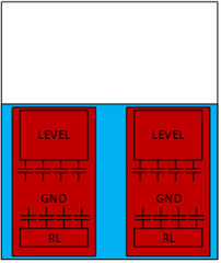
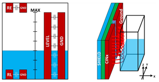
Please help check the schematic diagram below, thank you!

FDC1004DGSR_.pdf

  • Hello Reed,

    Can you provide some details on what the defect looks like?  Is there a large error in measurement or does the device not work at all after a period of time?

  • Patrick,  thanks!

    Is there a problem with the schematic?

  • Hello Reed,

    I don't see any serious issues with the schematic.  I do see you are using a 10uF where we suggest to use a 1uF tantulum + 0.1uF ceramic cap for decoupling the supply to gnd. However, I dont really expect that to cause any failures.  Its possible the issue is with the layout, can you share an image of that?

  • Hi Patrick,

    Attached is the PCB Layout file. Thank you!

    DRW65558_6.3_NEWPRO_WTS_PCB.PDF

  • Hello Reed,

    I see possible areas for improvement in the layout, but these still may not be what are causing the defect.  I would need more information on what the defect looks like to do any testing on my end.  As for the improvements, it might help to have the bottom layer (blue) shield2 plane match the top layer (red) shield2 plane. I think a few more stitching vias for the shield planes towards the center of the board would help. Also it might help to increase the distance between the GND signal and the shield2 plane.  Lastly I noticed J1 is located such that the connecting wires are probably draped right over the shield plane.  The shield should minimize the impact of these wires on the signal; however ensuring that those are a spaced a little further from the board surface or running directly over the sensor array might help with your results.

  • Patrick, 

    Here are two test videos to see if they are helpful.


  • Hey Reed,

    Thanks for providing the video.  The failure looks repeatable for that first device.  If you retest again in the same fixture and it fails again, it could be the device is damaged.  If after retesting it works again, then there could be some sort of issue with the communication lines or the program.  For repeatable failures you might consider submitting for Failure analysis.

  • Patrick,

    I have submitted a FA application, No. CPR231090159.

    The response is as follows:

    high failure rate, and the failing units are from different batch lot and even different manufacture time, no common was detected. as customer feedback, the IC didn't detect any voltage or pin resistance abnormal. highly suspected this is application related. suggest checking with board design team for test condition and PCB design.

  • Hello Patrick,

    Do you have any other suggestions?

    Thanks!

  • Reed,

    Perhaps the plates are inadequately large for the distance from the liquid container and the design did not have sufficient margin, so many but not all pass.  I would suggest putting the pcb flush with the container for the failing unit and see if it still fails the test.  Another thing you could do is provide the capacitance readings.  It would help to have reference readings from one good unit and then readings from the faulty unit.  I would then need to have some explanation on the threshold chosen for the different states.

    Based on the layout Im seeing, it looks like you are doing something like this:

    whereas some of the examples we have for liquid sensing look like this:

    Can you comment on the algorithm the software is using for determining container states?

    Also could you provide scope shots of the CINx pins?

  • Thanks Patrick, will let customer test it.