Because of the holidays, TI E2E™ design support forum responses will be delayed from Dec. 25 through Jan. 2. Thank you for your patience.

This thread has been locked.

If you have a related question, please click the "Ask a related question" button in the top right corner. The newly created question will be automatically linked to this question.

TDC7201: Unable to recognize start or stop signals

Part Number: TDC7201

Our client used TI's TDC7201 for the laser ranging project, and now they are encountering some problems. Do you have any solutions?

When using multiple TDC7021 chips, we found that some of them were OK, and those that were not felt as if they had not received the START signal. During debugging, we connected the START and STOP pins together, configured the register as START for rising edge triggering and STOP for falling edge triggering. We sent a PWM wave with adjustable pulse width through the microcontroller to trigger the start signal and stop signal of TDC to measure the PWM pulse width. We found that the TDC chip did not respond, and there was also a PWM wave in the foot of START measured with an oscilloscope, but there was no response. After reading back the register status of the chip through SPI, it was found that there were no issues. The register status is as follows:

TDCx_ ConfiG1 Register=0x93

TDCx_ ConfiG2 Register=0x40

TDCx_ INT_ Status Register=0x00

TDCx_ INT_ MASK Register=0x07

Specific operation process: After the device is powered on, lower the ENABLE for a period of time and then raise it. Use SPI to change the register states of TDC, and read each entry to ensure successful SPI writing. Then, send a PWM wave to excite the START and STOP pins, and measure the PWM pulse width. The general situation is that TDC does not have a timeout interrupt signal, nor does it receive a startup signal interrupt. It is not possible to send 100 PWM waves at once (the PWM pulse width during debugging is 200ns-10) μ About s), now one MCU in our project is connected to three TDC7201 at the same time. The start pins of these three TDC7201 are all connected to the same IO input, and the SPI is also controlled by the same SPI through chip selection.

  • Hi HY,

    Thank you for posting to the Sensors forum!

    Are you able to provide a waveform of the described behavior both for when the TDC7201 responds and does not respond, as well as the signal being sent to the device?

    Best,

    ~Alicia

  • 1. One of our boards has three TDC7201, of which two 7201 each have only one TDC that can successfully read the time. The other TDC of each of them receives a START and then times out and interrupts, unable to successfully receive a STOP signal; Both TDCs inside the third 7201 are OK.

    2. We suspect that the chip was not soldered properly, causing the STOP signal to not be received. Therefore, we tried to use a hot air gun to heat it up. The temperature of the hot air gun was 330 ℃, and the wind speed was very low. After heating for five minutes, we re measured and found that the TDC, which was still OK, could not even receive START (determined by the register status). Does temperature have an impact on TDC?

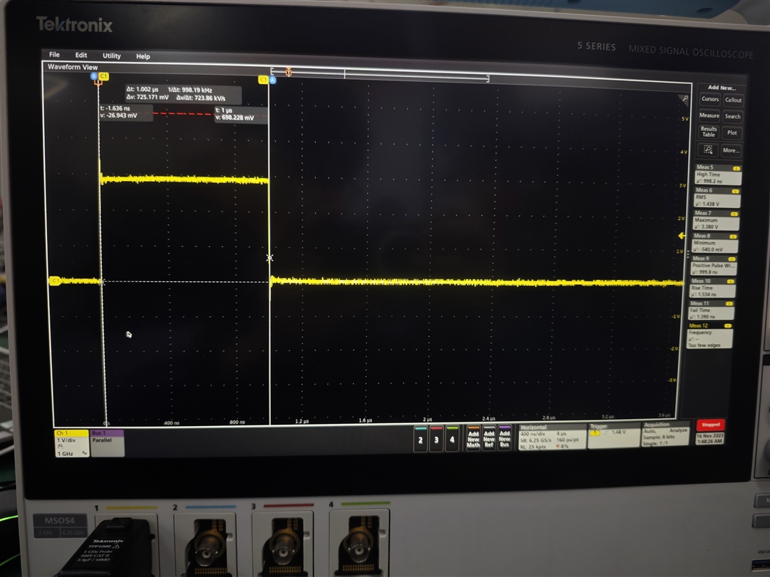
    3. The attachment is the PWM trigger signal we sent, with the rising edge as the START signal and the falling edge as the SIOP signal.

  • Hi HY,

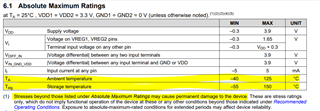
    Exposing the device to temperatures beyond what is specified in the Abs. Max. Rating table can cause permanent damage to the device, as specified below.

    I would recommend replacing the devices with new working devices and ensuring that they are soldered correctly to see if the problem still persists.

    Best,

    ~Alicia