This thread has been locked.

If you have a related question, please click the "Ask a related question" button in the top right corner. The newly created question will be automatically linked to this question.

AWRL1432: Where is the code location for doppler compensation?

Part Number: AWRL1432

Hi,

    I am working on the MMW demo in SDK 5.3, using BPM mode.

    The path is: C:\ti\MMWAVE_L_SDK_05_03_00_02\examples\mmw_demo\mmwave_demo

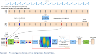
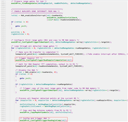
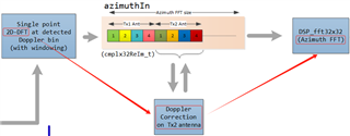
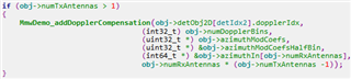
    In aoa2dproc.c, I didn't find the code about doppler compensation, could you please point out where doppler compensation is implemented? I may need to modify this code. 

Thank you.

  • Hi,

    Please give us some time to discuss with algorithm team

    thank you

    Cesar

  • Sorry for the delay

    Please see

    C:\ti\MMWAVE_L_SDK_05_03_00_02\source\datapath\dpu\aoa2dproc\v0\aoa2dproc.c

    Code after "Line 1508  aoa2dProc_findRangeGates"

    Please see Figure 21

    C:\ti\MMWAVE_L_SDK_05_03_00_02\docs\MmwaveDemo_documentation.pdf

    Thank you

    Cesar

  • Hi Cesar,

      I carefully checked the code and documentation but didn't find anything about Doppler compensation, which should be between the 2D FFT and the 3D FFT, that is, between the two functions aoa2dProc_ConfigAndTriggerHwaDopplerComputation(obj); and aoa2dProc_ConfigAndTriggerHwaAngleComp(obj);


      The following is what I found in the documentation and code of xwr16xx. What I am looking for is code similar to the function MmwDemo_addDopplerCompensation(). Could you please help me point out the location of the code?

    Thanks!

  • Hi,

    Yes, the doppler compensation algorithm implemented for AWRL1432 demo has been updated. It is no longer the same as for 16xx/18xx demo.

    Unfortunately, currently this is the only documentation we have available.

    Please give me some time to check with algorithm team if there is additional information available.

    Thank you

    Cesar

  • Hi,

    Here is some additional information

    "We just mentioned in the document that this is viewed as DDM (Doppler division multiplex) MIMO modulation scheme (although with only one sentence and even not explaining the acronym), so there is no Doppler compensation per se in the scheme. The received signal is superposition of the two reflections, coming from two transmitted antennas. One Tx antenna has a constant initial phase, the other has phase rotated by 180 degrees every chirp. The reflections from single target are separated in doppler spectrum by pi. For example a single stationary objects will have two peaks in the Doppler spectrum (N-point FFT where N is number of chirps in the frame): one at zero position (due to Tx antenna that does not have phase rotation) and other at p position (due to Tx antennas with phase rotation by 180 degrees). If the object is moving, these two peaks will be both shifted left or right by the same amount according the to the object radial velocity. So we just take the three symbols (of three Rx channels) from the first peak position, corresponding to the first 3 virtual antennas, and there symbols from the second peak position, corresponding to the other 3 virtual antennas, and perform the mapping for further processing (no need for Doppler compensation). Of course, the maximum unambiguous doppler frequency is from -N/4+1 to +N/4-1, assuming signed indices, or (0 to N4/1) for positive Doppler and (3N/4+1 to N-1) for negative doppler.


    Also note that the detection is performed on the range/doppler heat map where the Doppler FFT is performed per virtual antenna, where the doppler FFT size is N’ = N/2, and the detected indices are from (0 to N’-1) unsigned, or  (-N’/2 to to N’/2-1) signed."

    Thank you

    Cesar