This thread has been locked.

If you have a related question, please click the "Ask a related question" button in the top right corner. The newly created question will be automatically linked to this question.

LDC0851: What is the response time that can he expected when setup as a proximity sensor for non ferro metals.

Part Number: LDC0851
Other Parts Discussed in Thread: LDC1312, LDC1001, LDC1101

Couple of questions around this IC or recommended replacements 

Looking for experience on response times of these type of ICs. Are talking uS or Milliseconds ? 

Will they work with non ferromagnetic metals like lead  with 30mm coils. 

What will be better objecj moving through the center of the coil or parallel past the face of the coil(s) 

  • Hello, 

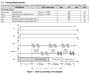
    The LDC0851 updates its output after each sensor conversion window. The conversion time is based on the sensor frequency used in the application. Sections 7.7 and 8.3.5 have more information about this timing. 

    For metal target, you can use a non-ferromagnetic metal as long as it is still conductive. In general, the more conductive the metal, the better the coupling to the sensor coils. It is also important to make sure that the metal target is at least 3 skin depths thick to ensure proper coupling. Since the skin depth is dependent on both sensor frequency and target conductivity, it is especially important to check this with lower conductivity metals like lead. 

    Assuming planar sensor coils on a PCB, it would be best to have the metal target running parallel to the sensor coils. You could do this with either sensor and reference side by side or stacked. If you have wire wound coils, it could be okay to pass the target through the center but it all depends on target shape and motion. 

    Best Regards, 
    Justin Beigel

  • Hey Justin 

    Thank you for the info,  does the frequency speed decrease the range the higher you go ? 

    Couple of questions 
    1) Will this split sense coil work?
    3) would the distance between the reference coil and the sensing coil matter  ? as in a 6 layer PCB layer 1 is C1, layer 3 is Ref coil and Layer 6 is C2 and the object passes through the center 
    4) I see the datasheet indicates 4 KSPS sample rate. with the split coil what is the maximum ( or minimum) time duration that could be measured in this step as I'm not sure how to calculate the rise and settling time of the output, especially if the target object is moving at speed. 
    Given the 4KSPS rate that would give maximum possible rate of 250uS?
    Im looking at setting up two of these coils( independent) at a fixed distance of 100mm and measure the detection time between both. The fastest time I would need to detect is
    100uS
    but looking at some configurations, Im wondering if splitting the sensing coil into two parts with reference coil in the middle would allow me to use a single driver for both sides. the distance could then be decreased
                        Object moving
     ===========---->============== 
    Coil1===1cm===Ref===1cm===Coil2
    | |__________________________________| |
    |                                                                        |
    Thank you 
  • Hello, 

    The frequency of the sensor coil is the resonant frequency of the inductive coil and capacitor combined. The max sensor frequency that the LDC0851 supports is 19MHz. The sensing range of the coil is determined by the sensor coil diameter. The larger the outer diameter, the longer the sensing range is. 

    I am unable to access the google drive link. Would you be able to upload the image to this thread? 

    The image may help answer this but can you clarify the use case/application you are using the device in? It would help to have a better understanding of the motion involved and the coil implementation. 

    On the note of splitting the coil into two to detect the object twice, this can work in some scenarios but you would need to make sure the total inductance of coil1 and 2 are able to match the inductance of the reference coil. 

    For the sample rate, it is based on the sensor frequency. For a 15MHz coil, you get a typical device conversion time of 290us. 

    Even at 4kSPS, you would not be able to guarantee detection of the target if it passes by both coils in 100us. If that is a hard requirement, the LDC1312 has a 13.3kSPS maximum channel sample rate but you would have to process the sensor data with an MCU. Is this something that could be considered for this application? 

    Best Regards, 
    Justin Beigel

  • I'm looking at the LDC1001 aswell see the sample rate is much much higher. I'm looking to build a chronograph. So 250uS is to slow. I need to be in the sub 100uS rage to have chance at winning with this. 

    The split coil idea is that the projectile will move over the first coil starting timer past the ref coil and then trigger the second portion of the coil. To stop the timer. I'm looking at a inductive solution to avoid optical issues with smoke and carbon builds up effecting readings. 
    So the projectile can pass with in 10mm of the coils and iv estimated the coil printed on flex PCB could be maximum of 30mm diameter but smaller and in FR4 would be prefered. A distance of 50mm between coil 1 and coil 2 would be prefered but can be made 100mm if if will be easier. 
  • Hello, 

    If you are considering the LDC1001, I would recommend the LDC1101 in place of it. It is a newer version of the device and supports a higher sample rate. You can configure the device to have an interrupt output when the inductance measurement trips above a programmed value. You would want to do the L comparator with hysteresis function to set this up.

    Just note that you wouldn't have a reference coil in the design so it would be just based on the inductance change at those two locations. From there, it is just making sure that you have enough inductance shift from your target at both locations to make it work. Keeping your split coils identical and matching the trace length of them would help with this. 

    Best Regards, 

    Justin Beigel

  • Thank you Justin, iv ordered the 1101 EVM todo some tests. Just a questions around the split coils. 

    Having two indetical coils,  connected in parallel to the input or having the two identical coils connected in series then to the input. 

    Along as the overall inductance/capacity is within limits does the one configuration have an advantage/impact over the other?

  • Hello, 

    The series vs parallel configuration also impacts the series resistance of the coil. It would be similar to the comparison made in section 2.3 of the Sensor Design for Inductive Sensing Applications Using LDC (Rev. C) app note. This talks about multiple coil layers, but it can translate into your split coils as well. 

    Best Regards, 

    Justin Beigel