This thread has been locked.

If you have a related question, please click the "Ask a related question" button in the top right corner. The newly created question will be automatically linked to this question.

PGA970: Erratic Phase Angle Reading

Part Number: PGA970


Currently I am using the PGA970 evaluation board connected to a 4-wire RVDT.

When I am reading out the phase angle via the GUI the phase angle seems to be jumping from 0-90 when the RVDT is fixed in a single position.

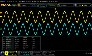
The excitation and return signals appear normal.

Other than setting the DAC_SIN_NDS2_1 = 0 and DAC_SIN_NDS2_1 = WAVEFORM_TABLE_LEN are there any other registers that may not be set correctly that would explain this behavior?

Thanks,

Nick

  • Hi Nick,

    I have never had good success when using the GUI to determine the phase.  The reason is the phase has to be computed and the PGA970 is not setup to do that type of calculation internally.  As to the GUI making that calculation, I have no idea what it is doing to make that computation and I have to make a manual computation based on the data.

    Perhaps the following post will be of some help:

    https://e2e.ti.com/support/sensors-group/sensors/f/sensors-forum/1263147/pga970-phase-detection-with-pga970evm-board/4788043?tisearch=e2e-sitesearch&keymatch=pga970%252520phase#4788043

    Best regards,

    Bob B

  • Hello Bob,

    Thank you for the reply.

    Sounds like the GUI isn't the best option for this.

    You mentioned setting up the PGA970 to do the calculation internally.  Am I correct in assuming this means to write my own code to do that calculation onboard the M0?  Is there any other registers I need to setup besides the two sampling registers for this calculation?

    Thanks,

    Nick

  • Hi Nick,

    Most customers that I have had contact with are making the measurements outside of the PGA970.  This is what the GUI should be doing, but the GUI is not working as it should.  If you were to make the computation within the PGA970, you would have to modify the firmware and use a more complicated communication using the COMBUF registers instead of reading directly.  Unfortunately due to resourcing limitations I cannot give you much support with the code.

    So I would suggest to at least start with the link I provided earlier and make the computations externally (or manually) so that you understand how the phase calculation works.  Besides setting up the waveform and the two DAC_SIN_NDSx registers, you will need to also configure the band-pass and low-pass filter settings as well.  You will also need two measurements to determine the phase.

    The phase result becomes arctan(DEMOD1_PH1DATA/DEMOD1_PH2DATA).

    Best regards,

    Bob B

  • Hello Bob,

    I went back and collected a few data points using the GUI and the Low Level Configuration screen.  I used the read_all function and then transfered the data into a spreadsheet to calculate the phase angle.

    As you can see for the 3 data points I have collected the phase angle changes from ~180-~54 degrees.  The waveforms on the scope still look nearly identical as before.

    DEMOD1_PH1_DATA1 DEMOD1_PH1_DATA2 DEMOD1_PH1_DATA3 DEMOD1_PH1_DATA4 PH1 DEMOD1_PH2_DATA1 DEMOD1_PH2_DATA2 DEMOD1_PH2_DATA3 DEMOD1_PH2_DATA4 PH2 PH1/PH2 Phase Angle
    7C FD FF FF 7CFDFFFF 36 0 0 0 36000 9480.889 179.9879134
    62 3 0 0 62300 80 2 0 0 80200 0.766341 74.92888518
    43 FE FF FF 43FEFFFF 83 FB FF FF 83FBFFFF 0.515183 54.51349934

    I made sure that the band-pass and low-pass filter were configured.

    Any other possibilities?

    Thanks,
    Nick

  • Hi Nick,

    The data is stored in the registers as little endian.  Unfortunately, this is only inferred in the datasheet and not clearly stated.

    Best regards.

    Bob B

  • Hello Bob,

    Thank you for the info.

    I swapped the data and recalculated the phase angle.  I still see that it drifts from ~90-~45.

    DEMOD1_PH1_DATA1 DEMOD1_PH1_DATA2 DEMOD1_PH1_DATA3 DEMOD1_PH1_DATA4 PH1 DEMOD1_PH2_DATA1 DEMOD1_PH2_DATA2 DEMOD1_PH2_DATA3 DEMOD1_PH2_DATA4 PH2 PH1/PH2 Phase Angle
    7C FD FF FF FFFFFD7C 36 0 0 0 00036 79536419 89.99999928
    62 3 0 0 00362 80 2 0 0 00280 1.353125 53.53448636
    43 FE FF FF FFFFFE43 83 FB FF FF FFFFFB83 1 45.0000047

    I would expect for a given input that doesn't appear to be changing that the registers for the phase data would be relatively stable. 

    Thanks,

    Nick

  • Hi Nick,

    One of the issues here is in how fast you can capture the data relative to the measurement.  When using the GUI, the reading of the register data is slow and that is why there are issues.  It is quite possible that the values between the phase measurements is overwritten for one of the phase measurements which creates the erratic response.

    Best regards,

    Bob B