This thread has been locked.

If you have a related question, please click the "Ask a related question" button in the top right corner. The newly created question will be automatically linked to this question.

AWR2243: Device sends repetitive 0xFFFF over SPI

Part Number: AWR2243

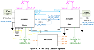
We have a cascaded radar designed based on the TI reference design and facing some issues with the bring up. We are in the process of configuring Master device.
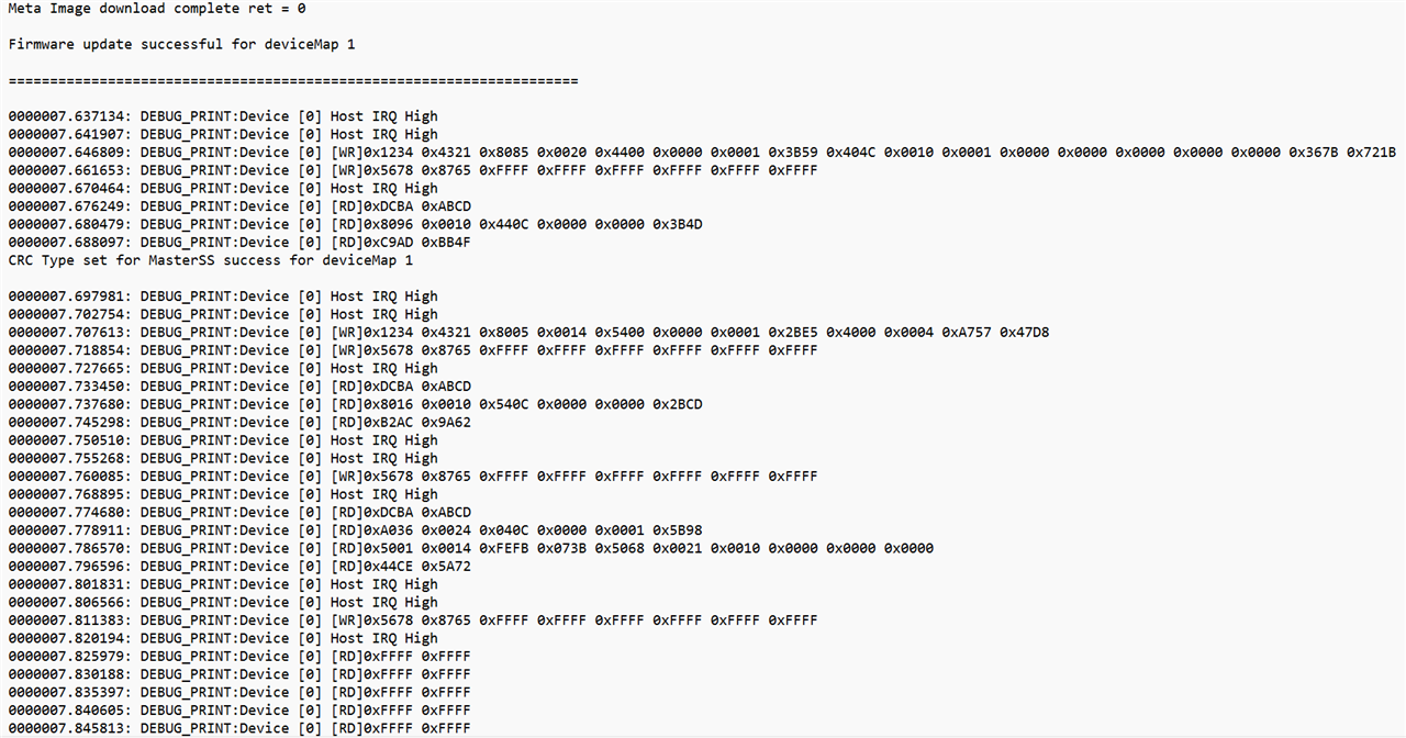
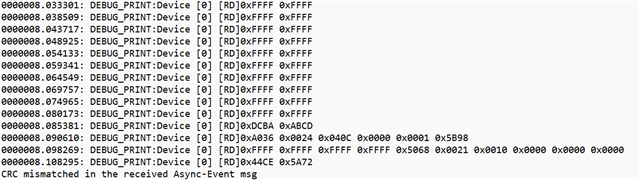
The issue is that after FW download gets completed, and during mmwl_rfenable, the device sends repetitive 0xFFFF to the host processor over SPI. The actual message arrives after lots of 0xFFFF but the application ends up with receiving checksum error which seem to be related to the junk 0xFFFF packets. We checked the MISO on a scope and it's all '1's for a long time.

Any idea what's going on?

  • Hello Daniel,

    Can you send me the log screenshot here? Also is this happening with all the AWR2243 you have? How many are cascaded in your board?

    Regards,
    Saswat Kumar

  • Saswat,

    We are using dual chip. We tried Master only for now.
    Here is the screenshot from the host processor side.

    Keeps sending 0xFFFF to the host processor, and then some partially valid data, finally the application reports the CRCmismatch/checksum error:

  • Hi Daniel,

    Please make sure that you have implemented below callback function in host application to check if HostIRQ is toggled down.

    * clientCtx.devCtrlCb.rlDeviceWaitIrqStatus = Host_deviceWaitIrqStatus;

    You need to implement Host_deviceWaitIrqStatus function at application which checks the GPIO status (connected to HostIRQ of AWR2243), based on 

    rlComIfHdl_t application needs to decide either AWR2243 master or slave device.

    .

    Host application must read the next response or async-event only after AWR2243 bring the HostIRQ down, which can be checked by above callback for mmWaveLink.

    .

    Regards,

    Jitendra

  • Thanks Jitendra.
    After looking into the issue further, we noticed that the Slave IRQ is not toggling correctly. For this device, we measured the IRQ voltage in L and H stats, and they are 2.7v and 3.3v, respectively, at the output of the device (Slave). Because of this issue, the IRQ handling was messed up in the processor. After excluding this IRQ, Master is booting up as expected. 

    Anyway, the IRQ from Slave stay at High level after reset and not responding to the processor. It changes from 3.3v to 2.7v which indicates a toggling is missing.

    Any idea what's going on? 

  • One more question, Jitendra. Can both the devices boot up simultaneously in single chip mode (non-cascaded) if the 40MHz clock is provided by Master?

  • Hi Daniel,

    I would request you to review your RF board with TI reference schematic (if any required pull up/down are missing on any pins)

    https://www.ti.com/tool/MMWCAS-RF-EVM#design-files

    .

    In the cascade scheme, slave device must power up only after Master device is up (post ChannelConfig API call).

    Master device enables the OSC_CLK_OUT to other slave device (as XTAL clock) at rlSetChannelConfig API call. So for given cascade setup master and slave devices can not be powered on together.

    (snapshot from AppNote).

    .

    Regards,

    Jitendra

  • Thanks Jitendra. We have reviewed the reference design, and it seems we comply with it.
    I understand that Master and Slave cannot boot up together, but can Slave boot up in standalone mode (single chip), after Master is up and functional? In the other word, does Master generate the OSC_CLKOUT in single chip mode too, or in it needs to be in cascaded mode only?

    Thanks!

  • Hi Jitendra,

    We are getting error 282 after sending the ChannelConfig API call to the Master device. The part number of the devices that we are using is AWR2243ABGABLQ1. From earlier posts, I see that this variant supports cascading:

    https://e2e.ti.com/support/sensors-group/sensors/f/sensors-forum/1201195/awr2243-awr2243?tisearch=e2e-sitesearch&keymatch=AWR2243ABGABLQ1%2520cascade#

    Does this part number support cascade? If so, why we are receiving this error?

  • Hi Daniel,

    Based on return value, looks like this sample is not meant for cascade.

    Let me check internally and get back by end of week.

    1. Meanwhile could you let me know the order date for these samples?

    2. provide output of rlGetRfDieId API (call to this AWR device from Host application)

    rlRfDieIdCfg_t dieId = { 0 };
    int retVal = rlGetRfDieId(RL_DEVICE_MAP_CASCADED_1, &dieId);  /* provide dieId value post this call returns */
    3. MSS & BSS Patch version
    rlVersion_t verArgs;
    retVal = rlDeviceGetVersion(RL_DEVICE_MAP_CASCADED_1, &verArgs); /* provide verArgs.rf structure values post this call returns */

    .

    Regards,

    Jitendra

  • 1- Order date: the AWR chips from a domestic supplier in China and it was placed on October 8th. The manufacturer confirmed that the data code is 2208+ and we are not certain if this information is useful for you.
    2- Output of rlGetRfDieId: will be provided shortly.
    3- FW version: provided as below:

    RF Version [ 2. 2. 0.13]
    MSS version [ 2. 2. 1. 7]
    mmWaveLink version [ 2. 2. 3. 2]

    RF Patch Version [ 2. 2. 4. 0]
    MSS Patch version [ 2. 2. 2. 0]

  • Hi Daniel,

    I'm checking with the team about sample shipment you received.

    Please allow me few more days (possible reply early Jan), as many of members are already OoO on vacation.

    .

    Regards,

    Jitendra

  • Hi Jitendra,

    Here is the output of rlGetRfDieId:

    Master: DieId [0x006036CC.0x00000009.0x0000001B.0x0000001B] Res [0x00000000.0x00000000.0x00000000.0x00000000]
    Slave: DieId [0x006036CC.0x00000005.0x00000015.0x00000027] Res [0x00000000.0x00000000.0x00000000.0x00000000]

  • Hi Jitendra,

    While we are waiting to get the analysis result on the other AWR chips, can you please confirm if the following configures 6Tx and 8Rx MIMO design in a 2-device radar config?

    Chirp Config api:
    //Master
    chirpCfgArgs->chirpStartIdx = 0;
    chirpCfgArgs->chirpEndIdx = 0;
    chirpCfgArgs->txEnable = 1;

    chirpCfgArgs->chirpStartIdx = 1;
    chirpCfgArgs->chirpEndIdx = 1;
    chirpCfgArgs->txEnable = 2;

    chirpCfgArgs->chirpStartIdx = 2;
    chirpCfgArgs->chirpEndIdx = 2;
    chirpCfgArgs->txEnable = 4;

    Chirp Config api:
    //Slave
    chirpCfgArgs->chirpStartIdx = 3;
    chirpCfgArgs->chirpEndIdx = 3;
    chirpCfgArgs->txEnable = 1;

    chirpCfgArgs->chirpStartIdx = 4;
    chirpCfgArgs->chirpEndIdx = 4;
    chirpCfgArgs->txEnable = 2;

    chirpCfgArgs->chirpStartIdx = 5;
    chirpCfgArgs->chirpEndIdx = 5;
    chirpCfgArgs->txEnable = 4;

    Frame Config api:
    //Master
    frameCfgArgs->chirpStartIdx = 0;
    frameCfgArgs->chirpEndIdx = 2; 

     Frame Config api:
    //Slave
    frameCfgArgs->chirpStartIdx = 3;
    frameCfgArgs->chirpEndIdx = 5; 

  • Hi Daniel,

    How are you trying to configure these 6 chirps -
          Are you trying to trigger them together? Or 
          Are you trying to trigger them one after another(trigger master first, and then trigger slave)?

    Case - I:  This configuration is fine if triggering together.

    Case - II:

    Otherwise in Case-II, create two structures of chirps. One for master MChirps[6] and another for slave SChirps[6]. Configure 6 chirps in each of them where
    For master enable 3 TX for first 3 chirps(chirp0-Tx0, chirp1-Tx1, chirp2-Tx2) and disable TXs for last 3 chirps.
    For slave disable TXs for first 3 chirps and enable TXs for last 3 chirps(chirp3-Tx0, chirp4-Tx1, chirp5-Tx2)

    This way you can trigger the chirps one after another(slave after master) manner. Because MIMO radar uses multiple transmitters and receivers at the same time.

    Thanks,
    Anirban