This thread has been locked.

If you have a related question, please click the "Ask a related question" button in the top right corner. The newly created question will be automatically linked to this question.

MMWAVEICBOOST: Not working

Part Number: MMWAVEICBOOST
Other Parts Discussed in Thread: IWR1443

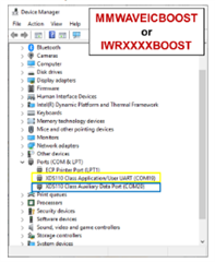
We recently received a replacement for the MMWAVEICBOOST and after the first use I was not able to either flash it or Collect data. 
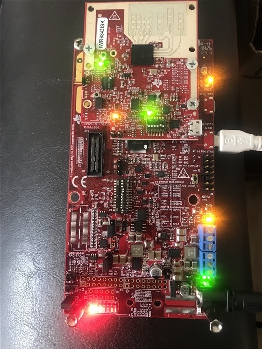
Ti team has mentioned that he could be the EVM but I do not know much about that. I’m using the same 5v power supply that we always used. 

this is the 3rd one already, And I’m starting to get frustrated and irritated about using this device. It’s slowing down my experiments, as well as the writing of my research paper process and also my team work as well.

  • Hi, I'm sorry you are having trouble working with the EVM. Here are a few questions to help debug the issue. 

    1. Have you followed this guide to ensure the board is set to the correct mode of operation for what you are trying to accomplish (flashing/functional mode)?

    2. Can you confirm the current rating for the power supply. Ideally this should be between 2.5-3 A.

    3. Is DS3 (NERR LED) on the MMWAVEICBOOST illuminated? It is hard to tell from your picture.

    Thanks and Regards,

    Josh

  •  Hello

    1. Yes tried both modes an nothing works, neither being recognized

    2. 


    3.only one light is on the one at the extreme left . Everything else is is barely on or not at all as you can see. 

  • Thank you. 

    neither being recognized

    When you say this do you mean that the serial ports do not show up on your computer after connecting the MMWAVEICBOOST via USB? Or the ports do show up but flashing fails? The ports should be seen in device manager as in the image below. 

    Additionally, there are 2 micro-USB ports on the MMWAVEICBOOST board. Please ensure that the USB connection to the PC is using the port labeled "XDS110 USB". 

    Also I just want to make sure that when you are testing this, you are using the correct switch settings for S1 on the ICBOOST to support ICBOOST+EVM operation. Based on your picture the settings look incorrect. The correct settings are listed on this page under the section mmWaveICBoost Initial Configuration. Are these the settings you have tested with?

    Best Regards,

    Josh

  • The device does not appear at all which means no ports are being found.

    And yes I did use the proper configuration prior to taking this picture. I would like to mention that This is not the first device we have worked with, but it’s the 3rd one, and we still have a functioning IWR1443.

    Thank you.

  • Hi, 

    Understood, thank you. I have assigned this thread to a HW expert who can help you debug further. Please give 24 hours for their response.

    Best Regards,

    Josh

  • Hi Mickael,

    I hope this is a follow up from the previous e2e thread below. Sorry to hear you are still facing this issue.

    (+) MMWAVEICBOOST: Device stopped working again - Sensors forum - Sensors - TI E2E support forums

    Kindly confirm the LED status here or in the previous e2e thread.

    D11 

    D14 

    DS1 

    D10 

    DS3 

    DS4

    Regards

    Ankit

  • Here is a picture of the previous replacement 

    And this is a close picture of the current replacement 

    D11 - low green  

    D14 - none 

    DS1 - red 

    D10 - none 

    DS3 - low red 

    DS4 - low yellow 

    correct me if I’m wrong 

  • Thank you, Mickael,

    I will check and confirm the status of the MMWAVEICBOOST board.

    Regards

    Ankit

  • Mickael, 

    Ankit has started winter vacation so I will be helping out in his absence.

    I've reviewed this thread history and the previous thread. 

    I have a few quick requests to help further diagnose the issues. 

    First, I see in your first post that you have an ISK module with a USB port. Please remove all USB debuggers, programmers, and devices (aside from your keyboard and mouse) from your PC. Disconnect your ISK module from your ICBOOST and connect it to your PC using it's USB port. 

    Do you see a COM port created when you plug it in? 

    If you do, that leads us to the next debug step. Disconnect the ISK from your PC, and then connect it to your ICBOOST. For now, please don't worry about the screws. Once it is secured to the ICBOOST, connect the XDS110 USB to your PC, and then connect the power supply to your PC. Do you see a COM Port get created? If so, what are the names of the ports? If not, Can you please make your device manager window as long as possible and take a screen cap of it? Please make sure to open any panels on USB devices, managers, and controllers. In addition, please open the COM port drop down, any drop down for unknown or unrecognized devices. An example of what I am looking for is shown below. You can send several captures if needed. 

    Thanks! 

    Blake 

  • Hello, I’m not currently in possession of the device. But About that first step, I did try it last time I was in the lab ( before filing the claim) I did try plugging only the 6843isk without the carrier board, and still nothing was shown, the laptop didn’t even make a sound of a device being plugged up. I have a windows laptop so no other devices was plugged. 

    I could try again next time, but it’s likely that it will be sometimes in January as I am done and off the project now. And if I cannot do it I’ll pass it along to the new students working with Dr. Sumit to get in touch with you guys. 

  • Hi Mickael,

    The D11 Green suggests the input is more than 5V, I suppose that being the root root cause for MMWACEICBOOST to go bad.


    See table 2-15 of 60GHz mmWave Sensor EVMs (Rev. E) (ti.com)

    To use a supply more than 5V please make these below changes.

    Regards

    Ankit

  • Hello, you got the wrong one ! This picture you using is from the 2nd replacement from months ago. 
    The current one is the main picture on top of thread. ( see the one with the sticky note)

  • Hi Mickael,

    The D11 LED glowing low green on current EVM also suggests that the power supply is greater than 5V. Please clarify if the same adaptor was used to supply the input voltage to both the boards.

    Regards

    Ankit

  • Hello,

    yes it is. And you can see the attached picture above as reference, which proves that it does produce the regular voltage needed and does not exceed it.

    Regards

  • Hi Mickael,

    Could you try the below workarounds to see if the issue is with the adapter.

    1. Kindly try replacing the power supply adapter with a new one and check if D11 is still glowing.

    2. Make the below assembly modifications and check if D11 is still glowing. (Short P3, P7 and remove R116)

    Regards

    Ankit