This thread has been locked.

If you have a related question, please click the "Ask a related question" button in the top right corner. The newly created question will be automatically linked to this question.

IWRL6432: Comparison about the performance of SPI with and without DMA

Part Number: IWRL6432

Hi,

Test Case: ES 2.0 EVM board (master)  to ES 2.0 customer board (slave) SPI transaction overnight test.

Test Content: Both master and slave send known data to each other to identify whether the received data is correct, if both master and slave receive the incorrect data the error count will increase, otherwise, the successful count will increase.

Question 1: Why does the performance between SPI with DMA and without DMA have a difference in error count? (I use the same code in the two cases)

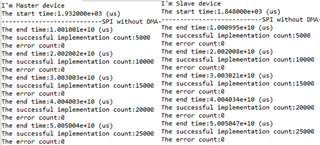
As the picture shows, SPI without DMA didn’t occur the error that both master or slave received the incorrect data.
But SPI with DMA has this error, As the picture shows. In here, the error count is different between the master and slave because the master receives correct data but the slave does not in a certain transaction.
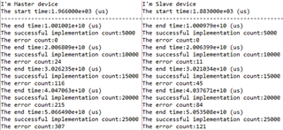
Question 2: According to the above two pictures, why the implementation time of SPI with DMA is almost the same as SPI without DMA? for my understanding that SPI with DMA should be quicker.

The implementation time = the end time - the start time

for example, the successful implementation count = 25,000 in SPI with DMA on the slave side

The implementation time = 5.0535e10(us) - 1.883e3(us) ≅ 50,535 (s) ≅ 14.03 (hrs)

in SPI without DMA on the slave side

The implementation time = 5.0050e10(us) - 1.848e3(us) ≅ 50,050(s) ≅ 13.9 (hrs)

  • Hello, 

    Please let me check internally on if there are any known issues with SPI DMA mode and get back to you in the next couple of days. 

    In the meantime I have a couple of questions. 

    1. Have you referred to the SPI and SPI DMA mode examples in the SDK? They are located at {MMWAVE_SDK5_INSTALL_DIR}/examples/drivers/mcspi. Please take a look if you have not already and compare with your code to confirm you are properly initializing the driver in your application. 

    2. I'm a bit confused about the reporting in your test. It seems that in all cases that you have shared, the successful implementation count remains the same. This is true even in the cases where errors are observed. Is this correct? Can you please clarify?

    Best Regards,

    Josh

  • Hi Josh,

    Have you referred to the SPI and SPI DMA mode examples in the SDK?


    Yes, I have run the example code and modified it a little bit that add the while loop to transfer continuously and print the error message if the data mismatch.

    Unfortunately, the example code has the same problem as my code.

    As the below figure, the byte inside the red circle is the incorrectly received byte, and the byte inside the yellow circle is the answer.

    As the below figure, the example code had 218 errors in 12,218 total executions

    Can you please clarify?


    Sorry that I didn't make it clear.

    the total executions = the successful implementation count + the error count, so the total executions = 25,000 (successful) + 307 (error) = 25,307

  • Hello, 

    Thank you for the clarification. I am still looking into this. I will update you when I have more information. Also, due to the upcoming holidays in the US much of the mmWave Radar Support team is out of the office right now. As such, responses may be delayed until the beginning of January. We appreciate your patience during this time.

    Best Regards,

    Josh

  • Hello,

    OK~, have a good Christmas holiday for all of you.

  • Hello, 

    Thank you. I apologize for the delay. We are still looking into this. Thank you for your patience.

    Best Regards,

    Josh

  • Hi, 

    I am very sorry about the delay here. Can you please let me know what SPI frequency this is running at when the issues are observed? Beyond certain frequency we have seen issues with MCSPI. 

    Best Regards,

    Josh

  • Hi,

    Can you please let me know what SPI frequency this is running at when the issues are observed

    About it, I didn't change SPI frequency and I didn't know where can change SPI frequency, so i think i always use defult vaule.
    Can you share this information to me about which frequency will happen issues?

  • Hello, 

    Sorry about the delayed response here. We have seen issues beyond 26 MHz. 

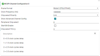
    Also, can you please try setting “TCS0” field of CHxCONF register to “3” and check if the issue persists? See section 13.7 of the IWRL6432 TRM for McSPI register descriptions.

    Best Regards, 

    Josh

  • Hi Josh,

    Sorry about the delayed response here. I have to do to test after following your suggestion, the result is shown below decriptions, in here, syscfg setting is shown on the below figure. SPI frequency = 1MHz and chip select TCS =3.

    -------------------------------------------------------------

    Master

    The end time:5.005017e+10 (us)
    The successful implementation count:25000
    The error count:0

    Slave

    The end time:5.004984e+10 (us)
    The successful implementation count:25000
    The error count:0

    -------------------------------------------------------------

    Below have some questions.

    1.Although the receive error didn't happen in the board-to-board transaction, but the spent time still similar to the SPI without DMA. Should be the speed of the SPI with DMA faster than the SPI without DMA, right?

    2.Why do we need to add a delay on the first or last edge of SPI clock, in order to guarantee the MCSPI peripheral is ready for a MCSPI transaction? or what kind of the timing requirement is required?

    3. why choose chip select TCS =3?  I guess the MCSPI transaction need 3.5 clock cycles delay be able to guarantee the MCSPI peripheral is ready, right?

    Thanks

  • Hello, 

    It's good to know that setting the TCS value to 3 resolves the errors that you were seeing. Please give me some time to find answers to your follow up questions and get back to you. 

    Best Regards,

    Josh

  • Hello, 

    I'm sorry for the delay here. 

    1.Although the receive error didn't happen in the board-to-board transaction, but the spent time still similar to the SPI without DMA. Should be the speed of the SPI with DMA faster than the SPI without DMA, right?

    Is there any other processing going on in your tests? If the test application is only continuously performing these SPI transactions then it would make sense that the times are similar because the time of the actual SPI transmission is the dominating factor and this does not change. SPI with DMA does not increase the speed of the SPI transmission but rather frees the main processor up to do other things while the DMA controller handles the SPI transmission. 

    Why do we need to add a delay on the first or last edge of SPI clock, in order to guarantee the MCSPI peripheral is ready for a MCSPI transaction? or what kind of the timing requirement is required?

    Having the delay makes sure that chip select is asserted first and SPI clock is detected by the McSPI after the CS assertion. This delay makes sure that the IP does not miss the first clock edge.

    why choose chip select TCS =3?  I guess the MCSPI transaction need 3.5 clock cycles delay be able to guarantee the MCSPI peripheral is ready, right?

    Having TCS=3 makes sure that this logic will work on all hardware. Having lesser TCS might create some problems on some hardware where the delay is not optimized. 

    Best Regards,

    Josh

  • Is there any other processing going on in your tests?

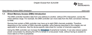
    No, only to do  SPI transmission, but why below figure say DMA controller can increase the throughput of peripherals?  the SPI interface is not included?

    Having the delay makes sure that chip select is asserted first and SPI clock is detected by the McSPI after the CS assertion. This delay makes sure that the IP does not miss the first clock edge

    I still don't understand what are the chip select and CS assertion, can you explain detail? and in here, IP indicates the core?

    In addition, missing the first clock edge will cause data loss, right?

    Having TCS=3 makes sure that this logic will work on all hardware. Having lesser TCS might create some problems on some hardware where the delay is not optimized

    Sorry, in here, logic stands for what? and can you provide some example about having lesser TCS might create some problems on some hardware?

  • Hi Josh,

    Excuse me, could you help me to clear the above questions?
    Thanks lot.

  • Hello,

    My apologies for the excessive delay. 

    why below figure say DMA controller can increase the throughput of peripherals?

    The wording in the TRM is not clear here. I will give this feedback to rectify the wording to reduce confusion. As previously mentioned SPI with DMA does not increase the speed of the SPI transmission but rather frees the main processor up to do other tasks while the DMA controller handles the SPI transmission. 

    Chip Select (CS) is an integral part of the SPI protocol. Please review SPI protocol to understand its meaning and usage. Also, yes IP is referring to the SPI IP core. 

    In addition, missing the first clock edge will cause data loss, right?

    This is correct. 

    Best Regards,

    Josh

  • Hi Josh,

    Thanks lot for your reply.

    I have benefited a lot.