A related question is a question created from another question. When the related question is created, it will be automatically linked to the original question.
If you have a related question, please click the "Ask a related question" button in the top right corner. The newly created question will be automatically linked to this question.
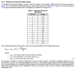
You can change the switching distance by adjusting the R2 resistor in your schematic. If you decrease it, you will decrease the ADJ code for the device and increase your switching distance. Section 8.3.3 of the datasheet has more information on this:
Keep in mind that the example in the datasheet uses a 49.9kOhm resistor and your implementation has a 51kOhm resistor when determining the ADJ code.
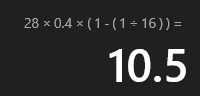
Based on your coil size being around 28mm, I would expect the switching distance to be 10.5 for an ADJ Code of 1:
However, this assume that the target is at least the same size of the coils. Is this the case for your application or is your target smaller than the coils? If not, can you explain the target interaction a bit more for your implementation?
For more information on the impact of the target size, please see the following:
The target of this circuit board induction is the bottom of the 304 stainless steel cup. The diameter of the bottom of the cup is 100mm, and the current coil diameter on the circuit board is 28mm;
Currently only 5-6mm, do you have any good suggestions?
Is there any metal near the sensor that isn't the intended target? If so, this could be the cause of the reduced range if the metal is closer than the target. You could try shielding the back side of the sensor coils with a ferrite sheet to focus the EM fields in the direction of the target in this case.
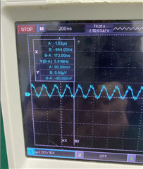
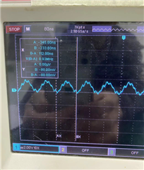
If this isn't the issue, then could you look as the sensors waveform on an oscilloscope and provide a screen capture?
There are no other metals near this induction circuit board. Below is a picture of the oscillation waveform during the operation of the induction board.
While you check on the PCB ground planes, can you also check on what the spacing is between your layers? Specifically the spacing between your sense and reference coils (between layers 2 and 3).
Also, one other thing to consider, are there multiple of these sensors next to each other? If so, having the identical coils near each other can cause them to couple and affect performance. Just want to double check to make sure this isn't an issue.