This thread has been locked.

If you have a related question, please click the "Ask a related question" button in the top right corner. The newly created question will be automatically linked to this question.

DRV421EVM: High DC accuracy ratio error

Part Number: DRV421EVM
Other Parts Discussed in Thread: DRV421,

Hello everyone,

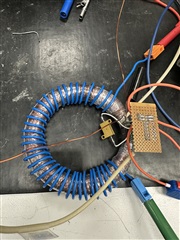
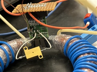
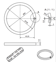
as I was asking about the suitable core for the DRV421 Evaluation Board, later we found one company who has succesfully produced this core for us. (see below).

The core is with Material Si - H085, magnet gain 660uT/A.

We are doing the DC current measurement with on this core now and there are unfortunately big ratio error between the primary current and the output voltage of the chip.

Here are some information about core windings and chip settings:

  • Number of compensation coil windings: 2000; Coil resistance: 18.5Ohm, inductance: 700mH
  • Rated primary current: 300A;
  • Chip refernce voltage: 2.5V;
  • Shunt resistance on the evaluation board, we have changed it into 1Ohm.
  • Primary windings: 36

Now the problems come, we have always measured a bigger voltage increase or decrease referenced to 2.5V as it should be. We measure the voltage on the Shunt-Resistance from the primary, multiply it to the windungs to get information of primary current. We also measure the output voltage directly from the chip. In the output range of 0-5V, if the primary current is positive, then the output will increase upper 2.5V, this increasment should be proportional to the primary current, vice versa. The ratio between output voltage and primary current should follow this formula:

V_out = V_ref +/- 4*R_shunt*I_comp

Some data from our measurement below:

-360A 1.681V
-60A 2.364V
-30A 2.432V
30A 2.571V
60A 2.636V
360A 3.325V

The measured error reachs near to 14% in this whole current range. The error doesn't vary a lot.

For example, the voltage with primary current at 360A should be: 

V_out = 2.5V + 4*1Ohm*360A /2000 = 3.22V

However, we measure 3.325V, which means an big error.

We have also tried another core with our parameters and the output voltage is tendential being bigger than it should. It is difficult to find the reason, afterall, we have checked the compensation windings and different stuffs on the evaluation board and no chance to find the problem out.

A lot of Thanks if we are getting some ideas or helps!!

Best Regards

Yutong

  • Hi Yutong,

    Thanks for the question and using the E2E forum.

    We're looking into this and will give you an update when we return from the holiday week.

    Louis

  • Hello Yutong,

    I have a couple of questions.  Where are the primary winding located?  I see your calculations don't take the 36 windings into account?  Are your 2000 windings distributed evenly around the core?  What is the tolerance of the 1Ω resistor you are using?  Why is your core so large?  Is your primary current a large conductors.  85mm seems large but you may have a reason for it.  

    The error in placement of the core should not cause much error but I would assume about 0.33% based on my simulations using permeability of 14000.  I could not find the your material's permeability but my simulation came close to your gain and inductance.  So this should not account for much error.

     Regards,

    Javier

  • Hello Javier,

    thank you for quick respond. Here are my answers to your questions.

    • The primary windings are wound homogenically around the core, like in this picture. We would like to have a rated primary current round about 300A ~ 500A.
    • I do take the 36 Windings into account, because our Amplifier can only generate a max. current of 25A, and the currents in my table (from -360A and 360A) are the currents already multiplied by the number of windings.
    • The resistor is not the problem, it is very precise.
    • The core size is defined by our core calculate engineer.

    It seems that the primary windings have big impact on the measurement and could be the reason that causing the error. Can you tell me if it is allowed to build the primary conductor as Ampere Windings like in this picture? Does the chip have problem to detect or work with magnetfeld from this kind of windings?

    Thank you in advance!

    Best regards

    Yutong

  • Hello Yutong,

    Your windings look good and that is how I would have done it.  I do not think that the error is coming from the primary windings.  

    Can you tell me if it is allowed to build the primary conductor as Ampere Windings like in this picture? Does the chip have problem to detect or work with magnetfeld from this kind of windings?

    Because you have the winding evenly distributed and a core that has high permeability the fields would be coupled through the core and should not be an issue.  Therefore the coupling to the DRV421 should go through the core as well.

    I don't see why you should have such a larger error. Below are some other things to look at.

    • Maybe look at how you are measuring your primary current.  Normally sources do not have good accuracy.  If you are using an external shunt or another measurement then this should be fine.  
    • Another thing is the magnetic coupling to the DRV421, could you show an image on the DRV421 inserted to your airgap?

    Regards,

    Javier

  • Hello Javier,

    yes, we used an external primary shunt to measure the current. We believe that the problem is caused by the primary windings. Yesterday we managed another Amplifier which can produce over 300A, and thus we don't need 36 Windings, instead, only one primary conductor, and the test results show the output Voltage from the Chip was without error, verified.

    However we still cannot understand the problem of primary windings. 

    What's the difference between producing 10A in 36 Windings, and producing 360A in one single primary conductor? Could that be different kind of magnetic fields near the air gap and the chip area which cause the problem?

    Because in the application note of the DRV421EVM, primary current is also through only one conductor, we guess maybe this chip is not working with ampere windings?

    Thanks and regards

    Yutong

  • Hello Yutong,

    This is the magnetic coupling should not matter either with windings or single primary.  

    What's the difference between producing 10A in 36 Windings, and producing 360A in one single primary conductor?

    There should not be a difference in this case and the magnetics should be the same.

    Could that be different kind of magnetic fields near the air gap and the chip area which cause the problem?

    This could be but with a decent permeability and your pictured setup I don't think it will be much.  The only issue that is possible is the Rshunt being placed close to the inside of the core.  

    Because in the application note of the DRV421EVM, primary current is also through only one conductor, we guess maybe this chip is not working with ampere windings?

    This should not be the case.  I don't understand why you are having issues and I have done this exact experiment when testing about 1000A.  

    Regards,

    Javier

  • Hello Javier,

    thanks a lot for the answer. For further tests we only used one single primary conductor and with the original DRV421EVM Board, without any changes. We got some good results with the ratio, but only in one single current direction, the results in other direction were still bad. The error is calculated between the measured value of primary and measured output voltage, which can be converted into the secondary current. It is weird because only one direction is good, and the error is always bigger at small current area.

    Ip [V] U_out [V] error (%)
    -40 0.1411 -1.7125
    -20.1 1.334 -3.3167
    -10.8 1.889 -5.7098
    -6.5 2.1474 -9.58974
    6.5 2.888 -0.5128
    10.8 3.146 -0.3086
    20.1 3.7031 -0.2404
    40 4.898 -0.0833

    We would like to send you some of our cores samples with compensation windings to your address, kindly request that you can help us test out our cores with your DRV421-Board, equippment and settings. It is hard to believe that this original board and chip cannot work properly with our cores, because our next step is actually develop a new product for the company with the board. Could you kindly give us a shipping address with your cost estimation on us? 

    Best regards

    Yutong

  • Hello Yutong,

    Following up offline.

  • Please see private message sent.