This thread has been locked.

If you have a related question, please click the "Ask a related question" button in the top right corner. The newly created question will be automatically linked to this question.

LDC1612: About measurement of heated inclined metal planes

Part Number: LDC1612

Hello,  I have two urgent questions about the use of LDC1612.
the first question:
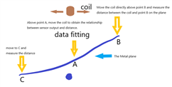
  I use LDC1612 to measure the unevenness of the metal plane. There are two processes required here. One is to establish the relationship between sensor output and distance, and the other is to use LDC1612 to measure the height value. There are three questions here:
    1. If the metal plane is inclined or the metal surface is uneven, use a coil to measure the inductance value and then convert it into a distance value. What does this distance value (inductance value) represent? Is it the average value of this inclined plane?


    2. If the inclination of the metal plane used to establish the relationship between the sensor and the distance is inconsistent with the inclination of the measured plane, is the distance value of the measured plane reliable? In other words, if I establish the relationship between the sensor output value and the distance on a plane with an inclination of 5°, then I use this relationship to measure the planes with an inclination of 0° and 10°. Is the calculated distance accurate? 

  3. LDC1612 can get 3 kinds of output, including RAW, inductance value and frequency value. When I want to get the distance between the sensor output and the measured surface (used to measure the distance between other positions and the sensor coil), what type of output should I use? Can all output values be used?


the second question:
  I use LDC1612 to measure a heated metal plane. Due to thermal radiation, the temperature of the coil plate of LDC1612 will change. What is the relationship between the output value of the sensor and the temperature of the coil plate? Is there any formula or related information?

Looking forward to your reply, thank you.

  • Max,

    First question:

    1. If the incline or roughness is small over the area just beneath the coil, you might be able to use the readings to estimate an average value of distance.
      If the incline or roughness is greater, then experimentation will be needed to develop strategies to estimate distance. 
    2. As a guess, this success of this approach will depend upon the distance between a single coil and the metal plane. 
      One approach to try would be to always make the minimum distance between the coil and the plane the same small value, independent of the degree of the plane's tilt. 
      By "small value" I mean 5% - 10% of the coil's diameter. 
      Another approach would be to use an array of sense coils. The variation in inductance over the arrays would give some info on the degree of tilt.
    3. The distance-to-device output relationship would need to be derived from experiment and captured in an external algorithm, or more likely a lookup table. 
      The Inductive Sensing Design Calculator Tool provides calculated estimates of the distance/inductance relationship to get you started, but it needs to be validated via a design & experiment.

    Second question: We don't have info on output value versus temperature. In general, the output will depend upon any potential conductance changes in the plate as the temperature changes.
    If the plate becomes less conductive as it heats, we could expect the coil inductance to increase because of a reduction in the plate's eddy currents.
    The device output could then reflect this decreasing inductance of the coil. 

    Regards,
    John

  • Hello.

      I move to point A on the metal plane, modify the distance between the coil and point A in the vertical direction, and obtain multiple sets of sensor output values and distance values. Then, through polynomial fitting, obtain the relationship between sensor output and distance d = f(sensor_output ).


      Move the coil above point B to get the output value adc_b of the sensor. Then calculate the distance between the coil and point B through the f(x) obtained above. Similarly, get the distance from point C.
      The algorithm is shown below.


        I have a question, is the relationship between the sensor output value and distance obtained at point A applicable to all other positions on the metal plane?
        I only need to get the flatness of the metal plane, not the absolute distance.
        If there is a problem with this method, is there any other way to use LDC1612 to measure the height difference at different positions on a metal plane?

      Looking forward to your reply, thank you.

  • John:

      Is there any way to compensate for the impact of different tilt angles on the output of the LDC1612? For example: assuming the coil is horizontal, when using it to measure planes with different tilt angles, if the tilt angle is relatively small, the data obtained is approximately equal to the average value. When it is tilted As the angle increases, the value obtained should be greater than the average value. Is there a way to calculate compensation for this difference?

  • Max,

    Unfortunately there is no easy way to calculate the changes due to different tilts. 
    The electromagnetic interaction between the coil and the plane is very difficult to model and calculate in a precise way.
    As a result, the distance/tilt dependence based on the interaction is also difficult to estimate.

    Depending on your project's priorities, it might be worth simulating your system in an E/M simulator.

    Regards,
    John

  • John,

    Metal surrounding the coil can affect eddy current sensor measurements.
    Excuse me:
      1. How to calculate the prohibited area around the coil, both horizontally and vertically?
      2. How does the surface area of metal affect the output of the eddy current sensor? Is there any relevant formula and explanation information?
      3. I have two metals of the same material but different surface areas. Is there any way to calculate the difference in measurement results while keeping the distance between the coil and the metal the same?

  • Max,

    We have no analytical tools to offer for the environment you describe.
    The most likely way to get the answers you are looking for is model your system's behavior in an E/M simulation tool.

    Regards,
    John

  • John,

      where is the E/M simulation tool and How to use it ?

    Regards,

    Max

  • Max,

    E/M tools are commercially available. 

    One - called FEMM is free.
    And there is an app note about using FEMM to simulate inductive sensors.

    regards,
    John