Hi all,
I would like to ask you the questions about the satasheets of FDS2214.
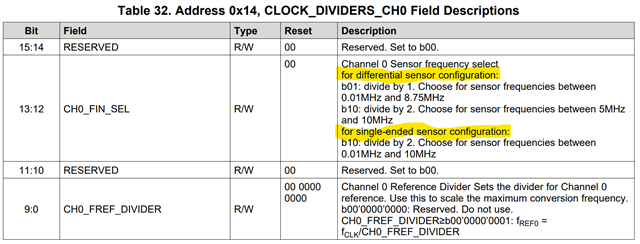
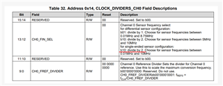
1)There are 2 notations of b10 in Table 32. Is the second one a mistake of b11?
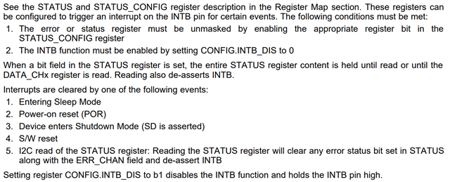
2) Do I need to retrieve STAUS at 0x18 and verify INTB before loading the data?
The FDC2214 provides measurement data from address 0x00~0x07.
When using EVM, STAUS was obtained from 0x18 before reading the data.
When STAUS is read, INTB signal is High automatically.
After a while, INTB will change to Low.
So I was reading the measurement data of 0x00~0x07 for the first time.
I could not find any description of the above process in the datasheet.
Best Regards,
Ryusuke