This thread has been locked.

If you have a related question, please click the "Ask a related question" button in the top right corner. The newly created question will be automatically linked to this question.

PGA460-Q1: Limiting the current of transducer.

Part Number: PGA460-Q1
Other Parts Discussed in Thread: PGA460

Hi,

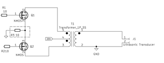
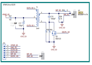
I want to enquire about PGA460 in section 8.2.1.1 Design Requirements, table 8-1. It says the transformer driving current rating is 500mA, how is this value determined? I want to use one of the recommended transformer, TDK EPCOS B78416A2232A003. I understand the maximum voltage is 200VAC but no mention of the current. I want to drive Ultrasonic transducer for example https://www.bjultrasonic.com/shop/40khz-50w-ultrasonic-cleaning-transducer-pzt4/ with input of 20V, since the transformer ration is 1:8.42, the output is expected to be 168.4VAC on the secondary, how can I limit the current to 300mA? Also is this transformer able to achieve resonance or do I need to add inductors 1mH to achieve so?

Kind regards,

Bright

  • The design application is for Ultrasonic cleaner. Thank you

  • Hi Bright,

    Thank you for posting to the Sensors forum!

    how is this value determined?

    This value is determined by the PGA460, please see below.

    how can I limit the current to 300mA?

    The PGA460 allows you to set a current limit between 50 mA to 500mA using CURR_LIM_P1, CURR_LIM_P12 as specified below is section 7.3.2.1 Using Center-Tap Transformer of the datasheet:

    Also is this transformer able to achieve resonance or do I need to add inductors 1mH to achieve so?

    Your transformer needs to be able to achieve the chosen frequency of the transducer in order to achieve resonance.

    Best,

    ~Alicia

  • Hi Alicia,

    Thank you for the answer. 

    Just to confirm if I am using B78416A2232A003-  frequency of 52kHz, and the ultrasonic transducer is rated 45kHz, in this sense, I do not need extra inductor as the transformer is able to achieve resonance, i.e., the transformer frequency is higher than the transducer.  But I only need to add inductor when the ultrasonic transducer frequency rating is higher than the transformer?

    Thank you for sharing those screenshot. However, I want to understand how the current limiting is done. Kindly refer to the block diagram 7.2 Functional Block Diagram in the datasheet. Is the current limiting done at the lower side connection of the MOSFET to GND? For example, by adding a resistor between their connection to ground as shown in the attached. In your case it is digitally controlled.  In other words, instead of adjusting the current limit via the register, I want to set it to 500mA and use trimmer connection to adjust it manually. 

    Also, concerning the connection to the transformer as shown in Figure 8-3. Typical Pinout of Center-Tap Transformer for Ultrasonic Transducers. Can I connect 1 and 3 to either OUTA or OUTB as mentioned in 8.2.1.2.4 Transformer Turns Ratio. In other words, Pin 3 can go to OUTA or OUTB and pin 1 can go to OUTA or OUTB?

    Kind regards,

    Bright

  • Hi Bright,

    Regarding your first question, my team and I have used other 40kHz transducers with the same transformer that you are referencing (B78416A2232A003) without any additional inductors, and it worked fine.

    For your second question, Figure 7-1 which shows a more detailed diagram of how current limiting works within the device which does include the usage of a resistor between the lower side connection of the MOSFET to GND. To help me better understand what you are trying to accomplish, could you expand on the reasoning behind using a trimmer connection to adjust the current limit manually instead of making this change with the register?

    For your last question regarding the center tap transformer, are you planning to use the Push-pull mode or the Single-ended mode?

    Best,

    ~Alicia

  • Hi Alicia,

    Thank you for your swift reply. 

    Oh yes, not using the inductor will safe space on the board.

    I want to adjust the current limit manually so I can easily set the desired current limit without programming the IC  each time and I need to make such adjust, and also am not proficient at coding, manually control is preferred at this time. 

    You mentioned that "it does include a resistor" Will connecting a resistor (R3) or a variable resistor be sufficient  to limit the current  manually as shown in the image below? or is there something else to needs to be done. 

    I am using push pull topology as described in the datasheet. 8.2.1.2.4 Transformer Turns Ratio

    Kind regards,

    Bright

  • Hi Bright,

    The resistor mentioned in my previous reply is internal to the device and is not accessible to the user. The easiest way to do this would be to program the IC with the necessary settings, which is something that will have to be done with the device as in order to start and stop measurements as well as make additional device related configurations. We do provide code examples, which can be found here, which can be used as a way to help you get started with the software side of things.

    Regarding the push-pull topology, the BOOSTXL-PGA460EVM actually uses the push-pull configuration with that same transformer (see image below), so I would recommend using that as a guideline. 

    Best,

    ~Alicia

  • Hi Alicia,

    Thank you for the email. 

    I want to use the IC to drive and ultrasonic transducer 40kHz for an ultrasonic cleaner only. I want to use similar  Arduino Uno chip (ATmega328P-A) to control the PGA-460-Q1, to select different frequency range, and limit current. How can I connect the PGA-460 IC to Arduino Uno similar for such control? In other words, what pins can I use for this connection? I see UART and GPIO to ECU on the PGA-460. 

    Also, since the application is only for ultrasonic cleaner, i.e., I am not receiving only transmitting, Do I need the External MOSFET? If you can X on your recement BOOSTXL-PGA460EVM diagram components that are not needed, that will be helpful, as there is no need to have redundant components. 

    Kind regards

    Bright

  • Hi Bright,

    The pins that you will need to interface to the PGA460 using UART are the TXD and RXD pins which you will need to connect to your Arduino's corresponding TXD and RXD pins.

    Given the current information, as you will not be receiving, you should not need the following pin connections for INN and INP. Additionally, I do not believe that you will need the DECPL and TEST pins, though I would recommend checking through the description of those pin functionalities just in case it may be applicable. To interface with this device, I would recommend using a standard UART interface as this would be the simplest programmatically, therefore, you would also not need the SCLK and IO pins. The sections/components that have been crossed out below are components that you should not need, given the current information provided.

    Best,

    ~Alicia

  • Hi Alicia,

    Thank you very much.

    Kind regards,

    Bright